6. Data Preparation
6.1. Introduction
This chapter describes how to prepare data for storage within the DTOcean database. Data representing sites and devices are covered in extended detail. Storage of sites and devices in the persistent database allows reuse across multiple projects. For sites this also gives access to automatic computational domain resizing.
A list of all database tables and their association to variables within DTOcean is given in the last section of the chapter. This includes the site and device tables, and the tables that store reference data to be used in all simulations. Data that is relevant only to a single project is not stored in the DTOcean database and is not discussed here.
6.2. Site
6.2.1. Conventions
The following conventions are used for site data used within DTOcean: [1]
- Depths are negative
- The datum for depths is mean sea level
- Wave directions are described using coming-from convention. Wave height and period conventions differ between variables.
- Current directions are described using going-to convention
- Wind speeds are measured at a reference height of 10m and the direction uses coming-from convention
6.2.2. Boundaries
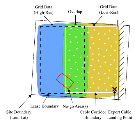
Fig. 6.1 Schematic of spatial site data
DTOcean uses two computational grids to store bathymetric, sedimentary and any environmental data that varies over the domain. The first grid covers the area where devices are to be deployed, known as the lease area, and the other covers the area where the export cable may be placed, known as the cable corridor. The lease area grid is normally of higher resolution than the cable corridor grid. The two areas must also overlap, as seen in Fig. 6.1, and, more precisely, contain coincident points. As such, it is recommended that the low resolution grid spacing be a multiple of the high resolution grid. Details regarding defining these grids is provided in the Grids section.
The extents of the grids are demarcated by two polygons, the lease boundary and cable corridor boundary. These polygons allow the user to modify the size of the computational domain and reduce the amount of grid data collected from the DTOcean database. Note, an overlapping region must be maintained when modifying the lease and cable corridor boundaries. The cable corridor landing point is also shown in Fig. 6.1, that marks the termination of the export cable at the shoreline. Although not a boundary, this should be included in the database so that the user can ensure it remains within the cable corridor following modifications. Within the lease area or cable corridor, additional polygons can be defined that excludes any grid points within them from computation. These areas are known as no-go areas and the user can define as many as required for a particular site.
All features described thus far are given in (UTM-like) conformal projection coordinates (see Grids). A final outer boundary, known as the site boundary, is defined using geodesic coordinates, to show the location of the site on a map. This is also why the polygon shown in Fig. 6.1 is slightly skewed.
Most of the features described above are stored in the project.site table of the DTOcean database (see the Database Tables section). An example entry to the table (following being dumped to a file) is shown in Table 6.1. The geo-spatial objects are represented as WKT strings, but are stored as binary objects in the DTOcean database itself. No-go areas are stored in the project.constraint and project.cable_corridor_constraint tables.
| Column | Example Row | Notes |
|---|---|---|
| id | 1 | |
| site_name | Eureka, CA | |
| lease_area_proj4_string | +proj=utm +zone=10 +ellps=WGS84 +datum=WGS84 +units=m +no_defs | See Grids |
| site_boundary | SRID=4326;POLYGON ((-124.15 40.75, -124.375 40.75, -124.375 40.925, -124.15 40.925, -124.15 40.75)) | WKT Polygon in WGS84 coordinates |
| lease_boundary | POLYGON ((391250 4517000, 386000 4520000, 391500 4529450, 396650 4526600, 391250 4517000)) | WKT Polygon in local projection coordinates |
| corridor_boundary | POLYGON ((398600 4518300, 392800 4521500, 395900 4527000, 401600 4524000, 398600 4518300)) | WKT Polygon in local projection coordinates |
| cable_landing_location | POINT (398575 4518325) | WKT Point in local projection coordinates |
6.2.3. Grids
DTOcean requires two Cartesian grids for describing data that varies over the lease area and cable corridor. These grids are drawn using a conformal projection, with units of metres, similar, but not restricted to, Universal Transverse Mercator (UTM) projections. When entering grid data into the DTOcean database, the projection used for the grids must also be included. DTOcean uses a Proj4 string to define projections. For instance,
+proj=utm +zone=10 +ellps=WGS84 +datum=WGS84 +units=m +no_defs
describes the WGS 84 / UTM zone 10N projection. Any conformal projection with units of metres is valid, but note that the validity of the projection is not checked by the software. The projection is stored in the project.site table of the DTOcean database (see the Boundaries section).
The data on the grid is stored in points at it’s vertices, as seen in Fig. 6.2. The spacing of the grid must be uniform in the x and y directions but can differ between them. When entering points into the DTOcean database, those which lie outside of the boundary polygon do not need to be included. When reading the grid from the database, DTOcean will add points with NaN value to create a rectangular grid. When exporting and importing grids using file formats such as NetCDF, these NaN points are included.

Fig. 6.2 Plan view of the computational grid
6.2.4. Bathymetry and Sediments
Grids may also be defined with multiple layers. These layers can be used to define sedimentary layers, time series, etc. Fig. 6.3 shows the schematic for the storage of sedimentary data in DTOcean. Two values for each layer of sediment are associated to every grid point – the depth at which the sediment layer starts and the sediment type for that layer. The depth of the first layer represents the seabed bathymetry and the last defined layer is assumed to have infinite depth. A minimum of one sediment layer must be provided.
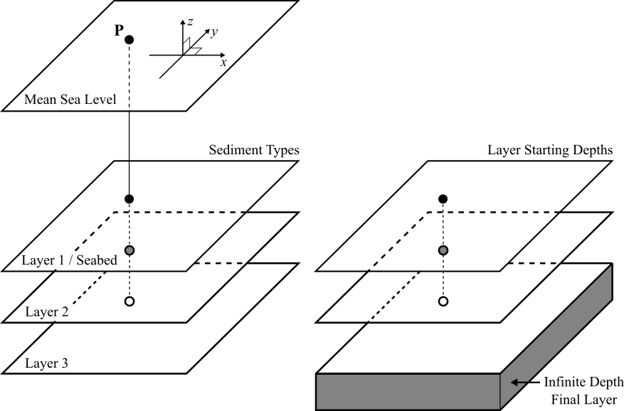
Fig. 6.3 Schematic of the data structure for describing sedimentary layers
The database definition of the sediment layers differs slightly from this definition, in that the distance of the start of each layer below the sea floor is used rather than the depth below sea level. An example of a single grid point definition, containing two sediment layers, defined in the project.bathymetry and project.bathymetry_layer tables, is show in Table 6.2 and Table 6.3.
The fk_bathymetry_id column in the bathymetry_layer table references the id column of the associated point in the bathymetry table. A reference to an id in the reference.soil_type table (shown in Table 6.4) is added to the fk_soil_type_id column of the bathymetry_layer table to select which sediment type belongs to the layer. Note, it is only necessary to include a value in the mannings_no column of the bathymetry table when the site will be used for tidal current energy extraction.
| Column | Example Row | Notes |
|---|---|---|
| id | 1 | |
| utm_point | POINT (391505 6651003) | WKT format (after dump) |
| depth | -50 | (m -ve) |
| mannings_no | 0.3 | Used only for tidal energy |
| Column | Layer 1 Example | Layer 2 Example | Notes |
|---|---|---|---|
| id | 1 | 2 | |
| fk_bathymetry_id | 1 | 1 | References id in Table 6.2 |
| fk_soil_type_id | 6 | 11 | References id in Table 6.4 |
| layer_order | 1 | 2 | Indexed from 1 |
| initial_depth | 0 | 10 | Measured from the sea floor (m +ve) |
| id | description |
|---|---|
| 1 | loose sand |
| 2 | medium sand |
| 3 | dense sand |
| 4 | very soft clay |
| 5 | soft clay |
| 6 | firm clay |
| 7 | stiff clay |
| 8 | hard glacial till |
| 9 | cemented |
| 10 | soft rock coral |
| 11 | hard rock |
| 12 | gravel cobble |
6.2.5. Environmental Data
6.2.5.1. Tidal Current Energy
When defining a site for tidal current energy extraction, layers of grid points are used to define the the currents throughout the domain. Table 6.5 shows an example of two hours of current data defined in the project.time_series_energy_tidal table for the example point shown in Table 6.2. Table 6.2 should also have the Manning’s number (mannings_no column) defined for each point in tidal current energy scenarios.
Common practice, thus far, is to prepare two weeks of hourly tidal current data (between the flood and neap tides). Thus the project.time_series_energy_tidal table will contain 336 rows for every grid point defined. This table is easily the largest stored within the DTOcean database and the user must take care that it does not become computationally unmanageable. The recommended upper limit is approximately \(5 \times 10^{6}\) rows (per site), and the grid resolution of the site should be adapted accordingly. For each entry to the time_series_energy_tidal table, the velocity components in the x and y directions (columns u and v respectively), the turbulence intensity and the sea surface elevation w.r.t. mean sea level (column ssh) must be provided.
| Column | Hour 1 Example | Hour 2 Example | Notes |
|---|---|---|---|
| id | 1 | 2 | |
| fk_bathymetry_id | 1 | 1 | References id in Table 6.2 |
| measure_date | 01/01/2016 | 01/01/2016 | |
| measure_time | 00:00:00 | 01:00:00 | |
| u | 2.1 | 2 | (m/s) |
| v | 1.05 | 1.05 | (m/s) |
| turbulence_intensity | 0.038586782 | 0.033037681 | |
| ssh | 0.35 | 0.35 | Sea surface elevation w.r.t. MSL (m) |
6.2.5.2. Wave Energy
For a site to be used for wave energy extraction, a time series at a single representative point (rather than the entire grid) is required; it is assumed that the wave conditions do not vary across the grid. Hourly values for the following quantities are required:
- significant wave height (\(H_{s}\))
- wave energy period (\(T_{e}\))
- wave direction
The duration of all series must match and it is recommended that at least one year of data is provided, but a longer period will result in improved energy production predictions. The series are stored in the project.time_series_energy_wave table. See the Database Tables section for further details.
6.2.5.3. Logistics
Representative time series are also needed for logistics calculations. Hourly values for the following quantities are required for a single representative point:
- significant wave height
- wave peak period (\(T_{p}\))
- surface current magnitude
- wind magnitude
The series must have matching durations and be at least one year in length, but longer periods are recommended. They are stored within the DTOcean database using the project.time_series_om_wave, project.time_series_om_tidal and project.time_series_om_wind tables. See the Database Tables section for further details.
6.2.5.4. Extremes
The extreme conditions within the lease area must be known for balance of plant design. The following information should be provided (the recommended return period is shown in brackets):
Long term sea surface current characteristics (10 year return period)
- Maximum
- Predominant direction
Long term wave characteristics (50 year return period)
- Maximum \(H_{s}\)
- Maximum \(T_{p}\)
- Predominant direction
- Representative gamma for a Jonswap spectrum
Long term wind characteristics (100 year return period)
- Maximum speed
- Predominant direction
- Maximum gust speed
- Predominant gust direction
Long term water level characteristics (50 year return period)
- Maximum
- Minimum
This data is stored in the project.lease_area table and further details can be found in the Database Tables section.
6.3. Device
6.3.1. Conventions and Dimensions
The following conventions are used when defining a device in DTOcean or its database: [1]
- Devices are categorised into one of four types: Wave or Tidal and Fixed or Floating
- Devices can have either Cylindrical or Rectangular profile
- Cylindrical devices are always orientated vertically (as in Fig. 6.4)
- The System Width variable describes the diameter of a cylindrical device. The System Length variable is unused.
- The local origin of a floating device lies on the waterline of the at-rest position of the device (see Fig. 6.4)
- The local origin of a fixed device lies at the base of the device (see Fig. 6.6)
- Height, width, length and draft are always given as absolute values
- Other dimensions are relative to the local origin
- For floating devices each foundation defined must have a matching fairlead on the device
- Floating devices must have an umbilical cable connection point defined
- A footprint must be given for floating devices, to describe the area swept by the device and its moorings. This can be given as a radius or a polygon in the local coordinate system.
- The vertical coordinate of foundation locations is unused
- Minimum and maximum installation depths are directional, i.e. the minimum depth is the deepest water in which the device can be deployed
- A minimum distance between devices in the x and y directions of the local coordinate system must be given
- Devices may yaw symmetrically up to an angle of 180 degrees
- Tidal devices may have two rotors, placed symmetrically perpendicular to the oncoming flow, in the horizontal plane
The name and type of a device is added to the project.device table (see the Database Tables section). The device_type column has four (case sensitive) values that can be used:
- Tidal Fixed
- Tidal Floating
- Wave Fixed
- Wave Floating
Examples of dimensions for floating and fixed devices (wave or tidal), having cylindrical and rectangular profile, respectively, are shown in Fig. 6.4, Fig. 6.5 and Fig. 6.6. The related nomenclature is given in Table 6.6.
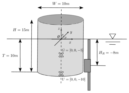
Fig. 6.4 Floating, cylindrical device dimensions example (side view)
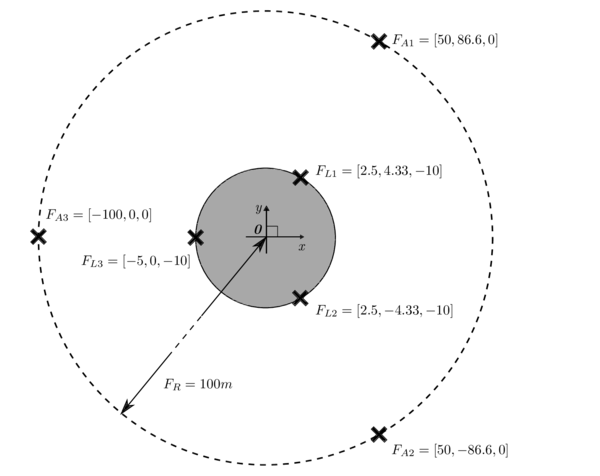
Fig. 6.5 Floating, cylindrical device dimensions example (top view)
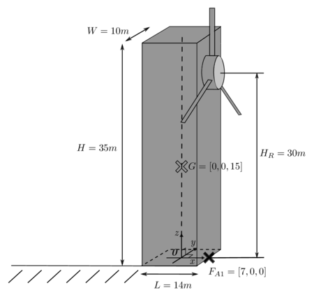
Fig. 6.6 Fixed, rectangular device dimensions example
| Symbol | Variable Name | Units | Notes |
|---|---|---|---|
| \(H\) | System Height | m | |
| \(W\) | System Width | m | Acts as diameter of cylindrical devices |
| \(L\) | System Length | m | |
| \(T\) | Floating Device Draft | m | Always positive |
| \(H_{R}\) | Tidal Device Hub Height | m | Tidal devices only |
| \(G\) | System Centre of Gravity | m | |
| \(U\) | Umbilical Cable Device Connection Point | m | Floating devices only |
| \(F_{L}\) | Fairlead Locations | m | Floating devices only |
| \(F_{A}\) | Device Foundation Locations | m | |
| \(F_{R}\) | Footprint Radius | m | Floating devices only |
Technology agnostic dimensions are added to the project.device_shared table of the DTOcean database. The profile column has only two (case sensitive) valid values which are:
- Cylindrical
- Rectangular
Floating device specific dimensions are added to the project.device_floating table. The depth_variation_permitted column of this table indicates if a vertical position of a floating device may vary. The valid values for this column are:
- yes
- no
Note that this value is superseded if the prescribed_mooring_system column is filled. The following (case sensitive) values can be used:
- Catenary
- Taut
Tidal device specific dimensions are stored in the project.device_tidal table. The rotor hub height and rotor diameter must be given in the hub_height and turbine_diameter columns, respectively. If the device has two rotors the turbine_interdistance column is used to describe the horizontal distance of the rotor hub from the device centre line (when orientated with the oncoming flow).
6.3.2. Power Conversion and Transmission
DTOcean requires the conversion performance of the simulated device to be
known prior to simulation. For wave devices, the performance data must be
calculated using the WEC Simulator tool (see the :ref:`tools` chapter).
This is necessary to allow calculation of the interactions between devices
within DTOcean. An output folder is produced by the tool, and the path to this
folder can be stored in the project.device_wave table of the DTOcean
database (see the Database Tables section).
For tidal energy devices, traditional power and thrust curves are required. These are entered into the project.device_tidal_power_performance table of the DTOcean database and an example of this table is shown in Table 6.7; a plot of this data is shown in Fig. 6.7. Cut-in and cut-out velocities are entered into the project.device_tidal table. Negative velocities may not be used in the performance curves, but the given power curve can be used for negative velocities if the two_ways_flow column of the project.device_tidal table is set to yes. If this value is no then no power will be produced for reversed flow through the rotor(s).
| id | velocity | thrust_coefficient | power_coefficient |
|---|---|---|---|
| 1 | 0 | 0.91 | 0 |
| 2 | 0.5 | 0.87 | 0.04 |
| 3 | 1 | 0.8 | 0.09 |
| 4 | 1.5 | 0.68 | 0.14 |
| 5 | 2 | 0.51 | 0.2 |
| 6 | 2.5 | 0.4 | 0.25 |
| 7 | 3 | 0.3 | 0.31 |
| 8 | 3.5 | 0.25 | 0.38 |
| 9 | 4 | 0.2 | 0.42 |
| 10 | 4.5 | 0.15 | 0.44 |
| 11 | 5 | 0.1 | 0.44 |
| 12 | 5.5 | 0 | 0 |
| 13 | 6 | 0 | 0 |
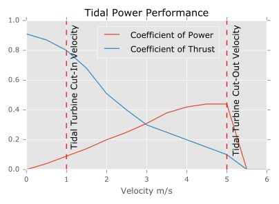
Fig. 6.7 Example tidal current device performance curves
Regardless of technology, the devices rated power and output voltage (U0) must be supplied. These values are added to the DTOcean database in the project.device_shared table. Note, any power generated above the device rating will be dumped. The type of connector used to couple the device to the electrical architecture must also be specified. The connector_type column has two valid (case sensitive) values:
- Wet-Mate
- Dry-Mate
A constant or variable power factor should also be given in the constant_power_factor or variable_power_factor columns, respectively. The variable power factor is given as a list of tuples defined as {power in pu, power factor}. An example entry to the variable_power_factor column may be:
{{1, 1}, {0.8, 0.9}, {0.5, 0.8}}
For floating devices the umbilical cable may be preselected using a value from the id column of the reference.component_cable. Only cables with fk_component_type_id column value 2 are valid. The id can be added to the prescribed_umbilical_type column of the project.device_floating table.
6.3.3. Sub-systems
For installation and life-time maintenance simulation, devices are divided into three or, optionally, four sub-systems. These sub-systems are:
- Support Structure: the main structural component of the device
- Prime Mover: the device’s source of motive power
- Power Take Off (PTO): the system responsible for conversion of motive power to electricity
- Control [optional]: computational / mechanical equipment for device motion control
Examples of how these sub-systems may be allocated in a tidal current or wave energy device are shown in Fig. 6.8 and Fig. 6.9.
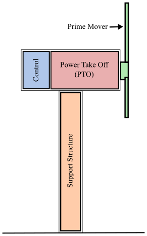
Fig. 6.8 Example sub-systems in a tidal current device
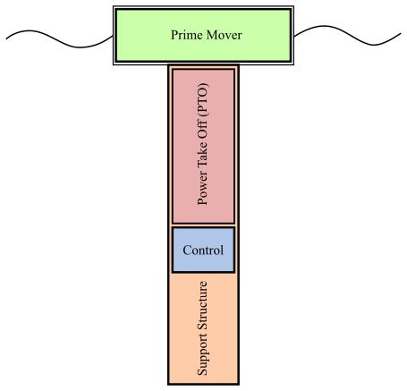
Fig. 6.9 Example sub-systems in a wave device
6.3.4. Installation
Installation of the device can be either as a single solid whole, or the support structure is installed first, followed by the remaining components. The choice is stored in the two_stage_assembly column of the project.device_shared table (see the Database Tables section) and can have values:
- yes
- no
How the device is transported to and from the deployment area is stored in the transportation_method column. This can have one of two (case sensitive) values:
- Deck
- Tow
If the device is to be towed then the bollard_pull column should also be filled.
The load_out_method column indicates how the device is transported from shore onto the vessel or into the water. It has four (case sensitive) valid values:
- Skidded
- Trailer
- Float Away
- Lift Away
Note that for the Deck transportation method, only the Skidded and Lift Away load-out methods are valid.
The duration required to assemble, connect and disconnect the device is added to the assembly_duration, connect_duration and disconnect_duration columns, respectively.
Installation information for the device sub-systems is stored in the project.sub_systems_install table, regardless of the choice in the two_stage_assembly column. This table dictates the allowable operational limit conditions (OLCs) when installing the device. An example entry to the table is shown in Table 6.8. Note that the fk_sub_system_id column should reference a value from the id column of the project.sub_systems table, which is shown in Table 6.9. Data for all device sub-systems to be simulated should be added.
| Column | Example Row | Notes |
|---|---|---|
| id | 1 | |
| fk_sub_system_id | 1 | References id in Table 6.9 |
| length | 20 | |
| width | 20 | |
| height | 4 | |
| dry_mass | 200000 | |
| max_hs | 2 | |
| max_tp | 99 | |
| max_ws | 15 | Wind speed magnitude |
| max_cs | 1.5 | Surface current speed magnitude |
| id | sub_system |
|---|---|
| 1 | Prime Mover |
| 2 | PTO |
| 3 | Support Structure |
| 4 | Control |
6.3.5. Maintenance
Each sub-system defined within DTOcean can have three types of maintenance operation. These are “Inspection”, “Maintenance” or “Replacement”. The appropriate types for each device sub-system, and how likely they are with respect to each other must be chosen. This is partly controlled by the values given in the project.sub_systems_operation_weightings table. A set of example entries to this table is shown in Table 6.10. An operation type can be excluded by using a value of zero for the required sub-system. Weightings can take any positive value; per sub-system, the likelihood of each operation will be calculated from the relative weights.
| id | fk_sub_system_id | maintenance | replacement | inspection |
|---|---|---|---|---|
| 1 | 1 | 1 | 1 | 2 |
| 2 | 2 | 1 | 0 | 2 |
| 3 | 3 | 0 | 1 | 10 |
The project.sub_systems_operation_weightings table determines which types of action are required when a sub-system failure is triggered, but the rate of failure is determined by the value of the failure_rate column in the project.sub_systems_economic table. An example set of entries to this table is shown in Table 6.11. Failures rates are supplied as the number of failures per \(1 \times 10^{6}\) hours.
| id | fk_sub_system_id | cost | failure_rate |
|---|---|---|---|
| 1 | 1 | 485000 | 4 |
| 2 | 2 | 400000 | 20 |
| 3 | 3 | 1200000 | 2 |
Detailed information for each required operation type for each device sub-system are entered into the project.sub_systems_inspection, project.sub_systems_maintenance and project.sub_systems_replace tables. An example row for the project.sub_systems_maintenance table is shown in Table 6.12. The columns of the other two tables are a subset of the columns of this table. As the device must be accessed for all maintenance actions, the columns in project.sub_systems_access table must also be filled for any sub-systems that undergo any operation type.
| Column | Example Row | Notes |
| id | 1 | |
| fk_sub_system_id | 1 | References id in Table 6.9 |
| operation_duration | 8 | |
| interruptible | yes | Can the operation be broken into parts? (yes or no) |
| parts_length | 1 | Parts required for maintenance |
| parts_width | 1 | 〃 |
| parts_height | 1 | 〃 |
| parts_dry_mass | 25 | 〃 |
| assembly_lead_time | 0 | Delays to commencement of operation in hours |
| crew_lead_time | 24 | 〃 |
| other_lead_time | 0 | 〃 |
| n_specialists | 1 | Two different wage levels are available |
| n_technicians | 4 | 〃 |
| max_hs | 2 | OLCs specific to this operation on this subsystem |
| max_tp | 99 | 〃 |
| max_ws | 15 | 〃 |
| max_cs | 1.5 | 〃 |
6.3.6. Economics
Storage of the cost of the whole device and each of its sub-systems within the DTOcean database is as follows:
- The whole device cost is stored in the cost column of the project.device_shared table
- The sub-systems costs are stored in the cost column of the project.sub_systems_economic table
6.4. Database Tables
All database tables used in the DTOcean database are listed here, alongside additional useful information. A typical table is described as follows:
- Table:
- The table name
- Approximate dump path:
- When using the database dump function, a tree of files
is generated. The path to the file representation of each table is given
here. As file types can vary, each path ends
.*. If the path contains a#then the tables has been split across multiple directories, sequentially numbered. - Linked to:
- If one of the columns in the given table references a column in another table, then the table name (or names) of the referenced tables are given here.
- See
- If relevant information is available elsewhere in the chapter then a link will be provided here.
Details relating to each column are presented in a table. The headings of the table have the following meanings:
| Column | The table column |
| Variable Name | The DTOcean variable name |
| Label | The sub-section of the variable (if used) |
| Unit | The SI unit |
6.4.1. Project Schema
Table: project.bathymetry
| Column | Variable Name | Label | Unit |
|---|---|---|---|
| id | |||
| utm_point | Bathymetry | ||
| depth | Bathymetry | m | |
| mannings_no | Manning’s Number |
Table: project.bathymetry_layer
site#\bathymetry\bathymetry_layer.*reference.soil_type; project.bathymetry| Column | Variable Name | Label | Unit |
|---|---|---|---|
| id | |||
| fk_bathymetry_id | |||
| fk_soil_type_id | |||
| layer_order | Bathymetry | ||
| initial_depth | Bathymetry | m |
Table: project.cable_corridor_bathymetry
site#\cable_corridor_bathymetry.*project.site| Column | Variable Name | Label | Unit |
|---|---|---|---|
| id | |||
| utm_point | Cable Corridor Bathymetry | ||
| depth | Cable Corridor Bathymetry | m |
Table: project.cable_corridor_bathymetry_layer
site#\cable_corridor_bathymetry\cable_corridor_bathymetry_layer.*reference.soil_type; project.cable_corridor_bathymetry| Column | Variable Name | Label | Unit |
|---|---|---|---|
| id | |||
| fk_bathymetry_id | |||
| fk_soil_type_id | |||
| layer_order | Cable Corridor Bathymetry | ||
| initial_depth | Cable Corridor Bathymetry | m |
Table: project.cable_corridor_constraint
site#\cable_corridor_constraint.*project.site| Column | Variable Name | Label | Unit |
|---|---|---|---|
| id | |||
| description | No Go Areas in Cable Corridor | ||
| boundary | No Go Areas in Cable Corridor |
Table: project.constraint
site#\constraint.*project.site| Column | Variable Name | Label | Unit |
|---|---|---|---|
| id | |||
| description | Nogo Areas | ||
| boundary | Nogo Areas |
Table: project.device
device.*| Column | Variable Name | Label | Unit |
|---|---|---|---|
| id | All Available Devices | id | |
| description | All Available Devices | description | |
| device_type | All Available Devices | device_type | |
| image |
Table: project.device_floating
device#\device_floating.*project.device| Column | Variable Name | Label | Unit |
|---|---|---|---|
| id | |||
| draft | Floating Device Draft | m | |
| maximum_displacement | Maximum System Displacement | m | |
| depth_variation_permitted | Floating Device Submersible Option | ||
| fairlead_locations | Fairlead Locations | m | |
| umbilical_connection_point | Umbilical Cable Device Connection Point | m | |
| prescribed_mooring_system | Mooring System Type | ||
| prescribed_umbilical_type | Predefined Umbilical Cable Identifier |
device#\device_shared.*project.device| Column | Variable Name | Label | Unit |
|---|---|---|---|
| id | |||
| height | System Height | m | |
| width | System Width | m | |
| length | System Length | m | |
| displaced_volume | System Submerged Volume | m^{3} | |
| wet_frontal_area | System Wet Frontal Area | m^{2} | |
| dry_frontal_area | System Dry Frontal Area | m^{2} | |
| wet_beam_area | System Wet Beam Area | m^{2} | |
| dry_beam_area | System Dry Beam Area | m^{2} | |
| centre_of_gravity | System Centre of Gravity | m | |
| mass | System Mass | kg | |
| profile | System Profile | ||
| surface_roughness | System Surface Roughness | m | |
| yaw | Device Heading Angle Span | deg | |
| prescribed_footprint_radius | Footprint Radius | m | |
| footprint_corner_coords | Device Footprint Coordinates | m | |
| installation_depth_max | Maximum Installation Water Depth | m | |
| installation_depth_min | Minimum Installation Water Depth | m | |
| minimum_distance_x | Minimum distance between devices in x direction | m | |
| minimum_distance_y | Minimum distance between devices in y direction | m | |
| prescribed_foundation_system | Preferred Foundation Type | ||
| foundation_locations | Device Foundation Locations | m | |
| rated_power | Device Rated Power | MW | |
| rated_voltage_u0 | Device Rated Voltage (U0) | V | |
| connector_type | Connector type for device | ||
| constant_power_factor | Device Constant Power Factor | ||
| variable_power_factor | Device Variable Power Factor | ||
| assembly_duration | Device Assembly Duration | hours | |
| connect_duration | Device Connect Duration | hours | |
| disconnect_duration | Device Disconnect Duration | hours | |
| load_out_method | Device Load Out Method | ||
| transportation_method | Device Transportation Method | ||
| bollard_pull | Device Towing Bollard Pull | tonnes | |
| two_stage_assembly | Two Stage Assembly | ||
| cost | Device Cost | Euro |
Table: project.device_tidal
device#\device_tidal.*project.device| Column | Variable Name | Label | Unit |
|---|---|---|---|
| id | |||
| cut_in_velocity | Tidal Turbine Cut-In Velocity | m/s | |
| cut_out_velocity | Tidal Turbine Cut-Out Velocity | m/s | |
| hub_height | Tidal Device Hub Height | m | |
| turbine_diameter | Turbine Rotor Diameter | m | |
| two_ways_flow | Bi-directional Turbine Boolean | ||
| turbine_interdistance | Interdistance Between Turbines | m |
Table: project.device_tidal_power_performance
device#\device_tidal_power_performance.*project.device| Column | Variable Name | Label | Unit |
|---|---|---|---|
| id | |||
| velocity | Turbine Performance Curves | Velocity | m/s |
| thrust_coefficient | Turbine Performance Curves | Coefficient of Thrust | |
| power_coefficient | Turbine Performance Curves | Coefficient of Power |
Table: project.device_wave
device#\device_wave.*project.device| Column | Variable Name | Label | Unit |
|---|---|---|---|
| id | |||
| wave_data_directory | Wave Data Directory |
Table: project.lease_area
site#\lease_area.*project.site| Column | Variable Name | Label | Unit |
|---|---|---|---|
| id | |||
| blockage_ratio | Site Blockage Ratio | ||
| tidal_occurrence_point | Tidal Occurrence Extraction Point | ||
| wave_spectrum_type | Wave Spectrum | ||
| wave_spectrum_gamma | Peak factor for Wave Spectrum | ||
| wave_spectrum_spreading_parameter | Spreading Parameter for Wave Spectrum | ||
| surface_current_flow_velocity | Maximum Tidal Stream Current Velocity in Lease Area | m/s | |
| current_flow_direction | Maximum Surface Current Direction | degrees | |
| moor_found_current_profile | Vertical Current Profile | ||
| significant_wave_height | Maximum Significant Wave Height | m | |
| peak_wave_period | Maximum Peak Wave Period | s | |
| predominant_wave_direction | Predominant Wave Direction | degrees | |
| jonswap_gamma | Maximum JONSWAP gamma | ||
| mean_wind_speed | Mean Wind Velocity | m/s | |
| predominant_wind_direction | Predominant Mean Wind Direction | degrees | |
| max_wind_gust_speed | Maximum Gust Wind Velocity | m/s | |
| wind_gust_direction | Predominant Direction of Max Gust | degrees | |
| water_level_max | Maximum Water Level | m | |
| water_level_min | Minimum Water Level | m | |
| soil_sensitivity | Soil Sensitivity | ||
| has_helipad | Array Helideck |
Table: project.site
site.*| Column | Variable Name | Label | Unit |
|---|---|---|---|
| id | All Available Sites | id | |
| site_name | All Available Sites | site_name | |
| All Landing Points | |||
| All Lease Boundaries | |||
| All Site Boundaries | |||
| All Cable Corridor Boundaries | |||
| lease_area_proj4_string | All Available Sites | lease_area_proj4_string | |
| site_boundary | All Site Boundaries | ||
| lease_boundary | All Lease Boundaries | ||
| corridor_boundary | All Cable Corridor Boundaries | ||
| cable_landing_location | All Landing Points |
Table: project.sub_systems
device#\sub_systems.*project.device| Column | Variable Name | Label | Unit |
|---|---|---|---|
| id | |||
| sub_system | Device Sub-System Costs | ||
| Device Access Requirements | Sub-System | ||
| Control Sub-System On-Site Maintenance Requirements | Sub-System | ||
| Device On-Site Maintenance Requirements | Sub-System | ||
| Device Replacement Requirements | Sub-System | ||
| Device On-Site Maintenance Parts Data | Sub-System | ||
| Control Sub-System Inspections Requirements | Sub-System | ||
| Device Sub-System Installation Specification | Sub-System | ||
| Device Control System Installation Specification | Sub-System | ||
| Control Sub-System Costs | |||
| Control Sub-System Replacement Requirements | Sub-System | ||
| Device Sub-System Failure Rates | |||
| Control Sub-System Access Requirements | Sub-System | ||
| Device Inspections Requirements | Sub-System | ||
| Device Operation Weightings | Sub-System | ||
| Control Sub-System Operation Weightings | Sub-System | ||
| Control Sub-System Failure Rates | |||
| Control Sub-System On-Site Maintenance Parts Data | Sub-System |
Table: project.sub_systems_access
device#\sub_systems\sub_systems_access.*project.sub_systems| Column | Variable Name | Label | Unit |
|---|---|---|---|
| id | |||
| fk_sub_system_id | |||
| operation_duration | Device Access Requirements | Operation Duration | hours |
| Control Sub-System Access Requirements | Operation Duration | hours | |
| max_hs | Device Access Requirements | Max Hs | m |
| Control Sub-System Access Requirements | Max Hs | m | |
| max_tp | Device Access Requirements | Max Tp | s |
| Control Sub-System Access Requirements | Max Tp | s | |
| max_ws | Device Access Requirements | Max Wind Velocity | m/s |
| Control Sub-System Access Requirements | Max Wind Velocity | m/s | |
| max_cs | Device Access Requirements | Max Current Velocity | m/s |
| Control Sub-System Access Requirements | Max Current Velocity | m/s |
Table: project.sub_systems_economic
device#\sub_systems\sub_systems_economic.*project.sub_systems| Column | Variable Name | Label | Unit |
|---|---|---|---|
| id | |||
| fk_sub_system_id | |||
| cost | Device Sub-System Costs | Euro | |
| Control Sub-System Costs | Euro | ||
| failure_rate | Device Sub-System Failure Rates | Failures per 10^{6} hours | |
| Control Sub-System Failure Rates | Failures per 10^{6} hours |
Table: project.sub_systems_inspection
device#\sub_systems\sub_systems_inspection.*project.sub_systems| Column | Variable Name | Label | Unit |
|---|---|---|---|
| id | |||
| fk_sub_system_id | |||
| operation_duration | Device Inspections Requirements | Operation Duration | hours |
| Control Sub-System Inspections Requirements | Operation Duration | hours | |
| crew_lead_time | Device Inspections Requirements | Crew Preparation Delay | hours |
| Control Sub-System Inspections Requirements | Crew Preparation Delay | hours | |
| other_lead_time | Device Inspections Requirements | Other Delay | hours |
| Control Sub-System Inspections Requirements | Other Delay | hours | |
| n_specialists | Device Inspections Requirements | Specialists Required | |
| Control Sub-System Inspections Requirements | Specialists Required | ||
| n_technicians | Device Inspections Requirements | Technicians Required | |
| Control Sub-System Inspections Requirements | Technicians Required | ||
| max_hs | Device Inspections Requirements | Max Hs | m |
| Control Sub-System Inspections Requirements | Max Hs | m | |
| max_tp | Device Inspections Requirements | Max Tp | s |
| Control Sub-System Inspections Requirements | Max Tp | s | |
| max_ws | Device Inspections Requirements | Max Wind Velocity | m/s |
| Control Sub-System Inspections Requirements | Max Wind Velocity | m/s | |
| max_cs | Device Inspections Requirements | Max Current Velocity | m/s |
| Control Sub-System Inspections Requirements | Max Current Velocity | m/s |
Table: project.sub_systems_install
device#\sub_systems\sub_systems_install.*project.sub_systems| Column | Variable Name | Label | Unit |
|---|---|---|---|
| id | |||
| fk_sub_system_id | |||
| length | Device Sub-System Installation Specification | Length | m |
| Device Control System Installation Specification | Length | m | |
| width | Device Control System Installation Specification | Width | m |
| Device Sub-System Installation Specification | Width | m | |
| height | Device Sub-System Installation Specification | Height | m |
| Device Control System Installation Specification | Height | m | |
| dry_mass | Device Sub-System Installation Specification | Dry Mass | kg |
| Device Control System Installation Specification | Dry Mass | kg | |
| max_hs | Device Sub-System Installation Specification | Max Hs | m |
| Device Control System Installation Specification | Max Hs | m | |
| max_tp | Device Sub-System Installation Specification | Max Tp | s |
| Device Control System Installation Specification | Max Tp | s | |
| max_ws | Device Sub-System Installation Specification | Max Wind Velocity | m/s |
| Device Control System Installation Specification | Max Wind Velocity | m/s | |
| max_cs | Device Sub-System Installation Specification | Max Current Velocity | m/s |
| Device Control System Installation Specification | Max Current Velocity | m/s |
Table: project.sub_systems_maintenance
device#\sub_systems\sub_systems_maintenance.*project.sub_systems| Column | Variable Name | Label | Unit |
|---|---|---|---|
| id | |||
| fk_sub_system_id | |||
| operation_duration | Device On-Site Maintenance Requirements | Operation Duration | hours |
| Control Sub-System On-Site Maintenance Requirements | Operation Duration | hours | |
| interruptible | Device On-Site Maintenance Requirements | Interruptable | |
| Control Sub-System On-Site Maintenance Requirements | Interruptable | ||
| parts_length | Device On-Site Maintenance Parts Data | Spare Parts Max Length | m |
| Control Sub-System On-Site Maintenance Parts Data | Spare Parts Max Length | m | |
| parts_width | Device On-Site Maintenance Parts Data | Spare Parts Max Width | m |
| Control Sub-System On-Site Maintenance Parts Data | Spare Parts Max Width | m | |
| parts_height | Device On-Site Maintenance Parts Data | Spare Parts Max Height | m |
| Control Sub-System On-Site Maintenance Parts Data | Spare Parts Max Height | m | |
| parts_dry_mass | Device On-Site Maintenance Parts Data | Spare Parts Mass | kg |
| Control Sub-System On-Site Maintenance Parts Data | Spare Parts Mass | kg | |
| assembly_lead_time | Device On-Site Maintenance Requirements | Spare Parts Preparation Delay | hours |
| Control Sub-System On-Site Maintenance Requirements | Spare Parts Preparation Delay | hours | |
| crew_lead_time | Device On-Site Maintenance Requirements | Crew Preparation Delay | hours |
| Control Sub-System On-Site Maintenance Requirements | Crew Preparation Delay | hours | |
| other_lead_time | Device On-Site Maintenance Requirements | Other Delay | hours |
| Control Sub-System On-Site Maintenance Requirements | Other Delay | hours | |
| n_specialists | Device On-Site Maintenance Requirements | Specialists Required | |
| Control Sub-System On-Site Maintenance Requirements | Specialists Required | ||
| n_technicians | Device On-Site Maintenance Requirements | Technicians Required | |
| Control Sub-System On-Site Maintenance Requirements | Technicians Required | ||
| max_hs | Control Sub-System On-Site Maintenance Requirements | Max Hs | m |
| Device On-Site Maintenance Requirements | Max Hs | m | |
| max_tp | Control Sub-System On-Site Maintenance Requirements | Max Tp | s |
| Device On-Site Maintenance Requirements | Max Tp | s | |
| max_ws | Control Sub-System On-Site Maintenance Requirements | Max Wind Velocity | m/s |
| Device On-Site Maintenance Requirements | Max Wind Velocity | m/s | |
| max_cs | Control Sub-System On-Site Maintenance Requirements | Max Current Velocity | m/s |
| Device On-Site Maintenance Requirements | Max Current Velocity | m/s |
Table: project.sub_systems_operation_weightings
device#\sub_systems\sub_systems_operation_weightings.*project.sub_systems| Column | Variable Name | Label | Unit |
|---|---|---|---|
| id | |||
| fk_sub_system_id | |||
| maintenance | Device Operation Weightings | On-Site Maintenance | |
| Control Sub-System Operation Weightings | On-Site Maintenance | ||
| replacement | Device Operation Weightings | Replacement | |
| Control Sub-System Operation Weightings | Replacement | ||
| inspection | Device Operation Weightings | Inspections | |
| Control Sub-System Operation Weightings | Inspections |
Table: project.sub_systems_replace
device#\sub_systems\sub_systems_replace.*project.sub_systems| Column | Variable Name | Label | Unit |
|---|---|---|---|
| id | |||
| fk_sub_system_id | |||
| operation_duration | Device Replacement Requirements | Operation Duration | hours |
| Control Sub-System Replacement Requirements | Operation Duration | hours | |
| interruptible | Device Replacement Requirements | Interruptable | |
| Control Sub-System Replacement Requirements | Interruptable | ||
| assembly_lead_time | Device Replacement Requirements | Spare Parts Preparation Delay | hours |
| Control Sub-System Replacement Requirements | Spare Parts Preparation Delay | hours | |
| crew_lead_time | Device Replacement Requirements | Crew Preparation Delay | hours |
| Control Sub-System Replacement Requirements | Crew Preparation Delay | hours | |
| other_lead_time | Device Replacement Requirements | Other Delay | hours |
| Control Sub-System Replacement Requirements | Other Delay | hours | |
| n_specialists | Device Replacement Requirements | Specialists Required | |
| Control Sub-System Replacement Requirements | Specialists Required | ||
| n_technicians | Device Replacement Requirements | Technicians Required | |
| Control Sub-System Replacement Requirements | Technicians Required |
Table: project.time_series_energy_tidal
site#\bathymetry\time_series_energy_tidal.*project.bathymetry| Column | Variable Name | Label | Unit |
|---|---|---|---|
| id | |||
| fk_bathymetry_id | |||
| measure_date | Tidal Time Series | ||
| measure_time | Tidal Time Series | ||
| u | Tidal Time Series | m/s | |
| v | Tidal Time Series | m/s | |
| turbulence_intensity | Tidal Time Series | ||
| ssh | Tidal Time Series | m |
Table: project.time_series_energy_wave
site#\time_series_energy_wave.*project.site| Column | Variable Name | Label | Unit |
|---|---|---|---|
| id | |||
| measure_date | Wave Time Series | ||
| measure_time | Wave Time Series | ||
| height | Wave Time Series | Hm0 | m |
| te | Wave Time Series | Te | s |
| direction | Wave Time Series | Dir | deg |
Table: project.time_series_om_tidal
site#\time_series_om_tidal.*project.site| Column | Variable Name | Label | Unit |
|---|---|---|---|
| id | |||
| measure_date | Tidal Current Time Series | ||
| measure_time | Tidal Current Time Series | ||
| current_speed | Tidal Current Time Series | Velocity | m/s |
Table: project.time_series_om_wave
site#\time_series_om_wave.*project.site| Column | Variable Name | Label | Unit |
|---|---|---|---|
| id | |||
| measure_date | Wave Time Series (Installation) | ||
| measure_time | Wave Time Series (Installation) | ||
| period_tp | Wave Time Series (Installation) | Tp | s |
| height_hs | Wave Time Series (Installation) | Hs | m |
Table: project.time_series_om_wind
site#\time_series_om_wind.*project.site| Column | Variable Name | Label | Unit |
|---|---|---|---|
| id | |||
| measure_date | Wind Speed Time Series | ||
| measure_time | Wind Speed Time Series | ||
| wind_speed | Wind Speed Time Series | Velocity | m/s |
6.4.2. Reference Schema
Table: reference.component
other\component.*| Column | Variable Name | Label | Unit |
|---|---|---|---|
| id | Collection Point Data | Key Identifier | |
| Mooring Forerunner Assembly Critical Failure Rates | Key Identifier | ||
| Mooring Swivel Non-Critical Failure Rates | Key Identifier | ||
| Wet Mate Connector Non-Critical Failure Rates | Key Identifier | ||
| Mooring Forerunner Assembly Data | Key Identifier | ||
| Foundation Drag Anchor Critical Failure Rates | Key Identifier | ||
| Power Transformer Data | Key Identifier | ||
| Foundation Pile Critical Failure Rates | Key Identifier | ||
| Static Cable Data | Key Identifier | ||
| Mooring Forerunner Assembly Non-Critical Failure Rates | Key Identifier | ||
| Foundation Pile Data | Key Identifier | ||
| Mooring Chain Non-Critical Failure Rates | Key Identifier | ||
| Wet Mate Connector Critical Failure Rates | Key Identifier | ||
| Dry Mate Connector Non-Critical Failure Rates | Key Identifier | ||
| Collection Points Foundation Locations | |||
| Mooring Shackle Data | Key Identifier | ||
| Dynamic Cable Data | Key Identifier | ||
| Collections Points Centre of Gravity | |||
| Collection Points Non-Critical Failure Rates | Key Identifier | ||
| Dry Mate Connector Data | Key Identifier | ||
| Foundation Drag Anchor Soft Coefficients | Key Identifier | ||
| Mooring Rope Critical Failure Rates | Key Identifier | ||
| Wet Mate Connector Data | Key Identifier | ||
| Dynamic Cable Non-Critical Failure Rates | Key Identifier | ||
| Foundation Drag Anchor Non-Critical Failure Rates | Key Identifier | ||
| Foundation Drag Anchor Sand Coefficients | Key Identifier | ||
| Mooring shackle Non-Critical Failure Rates | Key Identifier | ||
| Mooring Swivel Critical Failure Rates | Key Identifier | ||
| Mooring Chain Critical Failure Rates | Key Identifier | ||
| Mooring Rope Non-Critical Failure Rates | Key Identifier | ||
| Mooring Rope Data | Key Identifier | ||
| Mooring Swivel Data | Key Identifier | ||
| Mooring Rope Axial Stiffness Data | |||
| Static Cable Critical Failure Rates | Key Identifier | ||
| Dry Mate Connector Critical Failure Rates | Key Identifier | ||
| Transformers Critical Failure Rates | Key Identifier | ||
| Transformers Non-Critical Failure Rates | Key Identifier | ||
| Mooring Shackle Critical Failure Rates | Key Identifier | ||
| Dynamic Cable Critical Failure Rates | Key Identifier | ||
| Collection Points Critical Failure Rates | Key Identifier | ||
| Foundation Drag Anchor Data | Key Identifier | ||
| Mooring Chain Data | Key Identifier | ||
| Foundation Pile Non-Critical Failure Rates | Key Identifier | ||
| Static Cable Non-Critical Failure Rates | Key Identifier | ||
| description | Collection Point Data | Name | |
| Mooring Forerunner Assembly Data | Name | ||
| Static Cable Data | Name | ||
| Foundation Pile Data | Name | ||
| Power Transformer Data | Name | ||
| Dynamic Cable Data | Name | ||
| Mooring Shackle Data | Name | ||
| Foundation Drag Anchor Data | Name | ||
| Dry Mate Connector Data | Name | ||
| Wet Mate Connector Data | Name | ||
| Mooring Rope Data | Name | ||
| Mooring Swivel Data | Name | ||
| Mooring Chain Data | Name |
Table: reference.component_anchor
other\component\component_discrete\component_anchor.*reference.component_discrete; reference.component_type| Column | Variable Name | Label | Unit |
|---|---|---|---|
| id | |||
| fk_component_discrete_id | |||
| fk_component_type_id | |||
| connecting_size | Foundation Drag Anchor Data | Connecting Size | m |
| minimum_breaking_load | Foundation Drag Anchor Data | Min Break Load | N |
| axial_stiffness | Foundation Drag Anchor Data | Axial Stiffness | N/m |
| soft_holding_cap_coef_1 | Foundation Drag Anchor Soft Coefficients | Holding Capacity Coefficient 1 | |
| soft_holding_cap_coef_2 | Foundation Drag Anchor Soft Coefficients | Holding Capacity Coefficient 2 | |
| soft_penetration_coef_1 | Foundation Drag Anchor Soft Coefficients | Penetration Coefficient 1 | |
| soft_penetration_coef_2 | Foundation Drag Anchor Soft Coefficients | Penetration Coefficient 2 | |
| sand_holding_cap_coef_1 | Foundation Drag Anchor Sand Coefficients | Holding Capacity Coefficient 1 | |
| sand_holding_cap_coef_2 | Foundation Drag Anchor Sand Coefficients | Holding Capacity Coefficient 2 | |
| sand_penetration_coef_1 | Foundation Drag Anchor Sand Coefficients | Penetration Coefficient 1 | |
| sand_penetration_coef_2 | Foundation Drag Anchor Sand Coefficients | Penetration Coefficient 2 |
Table: reference.component_cable
other\component\component_continuous\component_cable.*| Column | Variable Name | Label | Unit |
|---|---|---|---|
| id | |||
| fk_component_continuous_id | |||
| fk_component_type_id | |||
| minimum_breaking_load | Static Cable Data | Min Break Load | N |
| Dynamic Cable Data | Min Break Load | N | |
| minimum_bend_radius | Static Cable Data | Min Bend Radius | m |
| Dynamic Cable Data | Min Bend Radius | m | |
| number_conductors | Static Cable Data | Number of Conductors | |
| Dynamic Cable Data | Number of Conductors | ||
| number_fibre_channels | Static Cable Data | Number of Fibre Optic Channels | |
| Dynamic Cable Data | Number of Fibre Optic Channels | ||
| resistance_dc_20 | Static Cable Data | DC Resistance | Ohm/km |
| Dynamic Cable Data | DC Resistance | Ohm/km | |
| resistance_ac_90 | Static Cable Data | AC Resistance | Ohm/km |
| Dynamic Cable Data | AC Resistance | Ohm/km | |
| inductive_reactance | Static Cable Data | Inductive Reactance | Ohm/km |
| Dynamic Cable Data | Inductive Reactance | Ohm/km | |
| capacitance | Static Cable Data | Capacitance | uF/km |
| Dynamic Cable Data | Capacitance | uF/km | |
| rated_current_air | Static Cable Data | Rated Current in Air | A |
| Dynamic Cable Data | Rated Current in Air | A | |
| rated_current_buried | Static Cable Data | Rated Current if Buried | A |
| Dynamic Cable Data | Rated Current if Buried | A | |
| rated_current_jtube | Static Cable Data | Rated Current in J Tube | A |
| Dynamic Cable Data | Rated Current in J Tube | A | |
| rated_voltage_u0 | Static Cable Data | Rated Voltage (U0) | V |
| Dynamic Cable Data | Rated Voltage (U0) | V | |
| operational_temp_max | Static Cable Data | Max Temperature | C |
| Dynamic Cable Data | Max Temperature | C |
Table: reference.component_collection_point
other\component\component_discrete\component_collection_point.*reference.component_type; reference.component_discrete| Column | Variable Name | Label | Unit |
|---|---|---|---|
| id | |||
| fk_component_discrete_id | |||
| fk_component_type_id | |||
| wet_frontal_area | Collection Point Data | Wet Frontal Area | m^{2} |
| dry_frontal_area | Collection Point Data | Dry Frontal Area | m^{2} |
| wet_beam_area | Collection Point Data | Wet Beam Area | m^{2} |
| dry_beam_area | Collection Point Data | Dry Beam Area | m^{2} |
| maximum_water_depth | Collection Point Data | Max Water Depth | m |
| orientation_angle | Collection Point Data | Orientation Angle | deg |
| input_lines | Collection Point Data | Input Lines | |
| output_lines | Collection Point Data | Output Lines | |
| input_connector_type | Collection Point Data | Input Connector Type | |
| output_connector_type | Collection Point Data | Output Connector Type | |
| number_fibre_channels | Collection Point Data | Number of Fibre Optic Channels | |
| voltage_primary_winding | Collection Point Data | Primary Winding Voltage | V |
| voltage_secondary_winding | Collection Point Data | Secondary Winding Voltage | V |
| rated_operating_current | Collection Point Data | Rated Current | A |
| operational_temp_min | Collection Point Data | Min Temperature | C |
| operational_temp_max | Collection Point Data | Max Temperature | C |
| foundation_locations | Collection Points Foundation Locations | Key Identifier | |
| centre_of_gravity | Collections Points Centre of Gravity | Key Identifier | m, m, m |
Table: reference.component_connector
other\component\component_discrete\component_connector.*reference.component_type; reference.component_discrete| Column | Variable Name | Label | Unit |
|---|---|---|---|
| id | |||
| fk_component_discrete_id | |||
| fk_component_type_id | |||
| maximum_water_depth | Wet Mate Connector Data | Max Water Depth | m |
| Dry Mate Connector Data | Max Water Depth | m | |
| number_contacts | Wet Mate Connector Data | Number Of Contacts | |
| Dry Mate Connector Data | Number Of Contacts | ||
| number_fibre_channels | Wet Mate Connector Data | Number of Fibre Optic Channels | |
| Dry Mate Connector Data | Number of Fibre Optic Channels | ||
| mating_force | Wet Mate Connector Data | Mating Force | N |
| Dry Mate Connector Data | Mating Force | N | |
| demating_force | Wet Mate Connector Data | Demating Force | N |
| Dry Mate Connector Data | Demating Force | N | |
| rated_voltage_u0 | Wet Mate Connector Data | Rated Voltage (U0) | V |
| Dry Mate Connector Data | Rated Voltage (U0) | V | |
| rated_current | Wet Mate Connector Data | Rated Current | A |
| Dry Mate Connector Data | Rated Current | A | |
| cable_area_min | Wet Mate Connector Data | Min Cable Area | mm^2 |
| Dry Mate Connector Data | Min Cable Area | mm^2 | |
| cable_area_max | Wet Mate Connector Data | Max Cable Area | mm^2 |
| Dry Mate Connector Data | Max Cable Area | mm^2 | |
| operational_temp_min | Wet Mate Connector Data | Min Temperature | C |
| Dry Mate Connector Data | Min Temperature | C | |
| operational_temp_max | Wet Mate Connector Data | Max Temperature | C |
| Dry Mate Connector Data | Max Temperature | C |
Table: reference.component_continuous
other\component\component_continuous.*reference.component| Column | Variable Name | Label | Unit |
|---|---|---|---|
| id | |||
| fk_component_id | |||
| diameter | Static Cable Data | Diameter | m |
| Foundation Pile Data | Diameter | m | |
| Dynamic Cable Data | Diameter | m | |
| Mooring Forerunner Assembly Data | Diameter | m | |
| Mooring Chain Data | Diameter | m | |
| Mooring Rope Data | Diameter | m | |
| dry_mass_per_unit_length | Foundation Pile Data | Dry Mass per Unit Length | kg/m |
| Static Cable Data | Dry Mass per Unit Length | kg/m | |
| Dynamic Cable Data | Dry Mass per Unit Length | kg/m | |
| Mooring Forerunner Assembly Data | Dry Mass per Unit Length | kg/m | |
| Mooring Rope Data | Dry Mass per Unit Length | kg/m | |
| Mooring Chain Data | Dry Mass per Unit Length | kg/m | |
| wet_mass_per_unit_length | Foundation Pile Data | Wet Mass per Unit Length | kg/m |
| Static Cable Data | Wet Mass per Unit Length | kg/m | |
| Dynamic Cable Data | Wet Mass per Unit Length | kg/m | |
| Mooring Forerunner Assembly Data | Wet Mass per Unit Length | kg/m | |
| Mooring Rope Data | Wet Mass per Unit Length | kg/m | |
| Mooring Chain Data | Wet Mass per Unit Length | kg/m | |
| cost_per_unit_length | Foundation Pile Data | Cost per Unit Length | Euro/m |
| Static Cable Data | Cost per Unit Length | Euro/m | |
| Dynamic Cable Data | Cost per Unit Length | Euro/m | |
| Mooring Forerunner Assembly Data | Cost per Unit Length | Euro/m | |
| Mooring Rope Data | Cost per Unit Length | Euro/m | |
| Mooring Chain Data | Cost per Unit Length | Euro/m |
Table: reference.component_discrete
other\component\component_discrete.*reference.component| Column | Variable Name | Label | Unit |
|---|---|---|---|
| id | |||
| fk_component_id | |||
| length | Dry Mate Connector Data | Depth | m |
| Power Transformer Data | Depth | m | |
| Mooring Swivel Data | Depth | m | |
| Wet Mate Connector Data | Depth | m | |
| Foundation Drag Anchor Data | Depth | m | |
| Mooring Shackle Data | Depth | m | |
| Collection Point Data | Depth | m | |
| width | Wet Mate Connector Data | Width | m |
| Dry Mate Connector Data | Width | m | |
| Mooring Swivel Data | Width | m | |
| Collection Point Data | Width | m | |
| Power Transformer Data | Width | m | |
| Mooring Shackle Data | Width | m | |
| Foundation Drag Anchor Data | Width | m | |
| height | Dry Mate Connector Data | Height | m |
| Mooring Swivel Data | Height | m | |
| Collection Point Data | Height | m | |
| Wet Mate Connector Data | Height | m | |
| Power Transformer Data | Height | m | |
| Mooring Shackle Data | Height | m | |
| Foundation Drag Anchor Data | Height | m | |
| dry_mass | Dry Mate Connector Data | Dry Mass | kg |
| Mooring Swivel Data | Dry Unit Mass | kg | |
| Collection Point Data | Dry Mass | kg | |
| Wet Mate Connector Data | Dry Mass | kg | |
| Power Transformer Data | Dry Mass | kg | |
| Mooring Shackle Data | Dry Unit Mass | kg | |
| Foundation Drag Anchor Data | Dry Unit Mass | kg | |
| wet_mass | Wet Mate Connector Data | Wet Mass | kg |
| Dry Mate Connector Data | Wet Mass | kg | |
| Power Transformer Data | Wet Mass | kg | |
| Mooring Swivel Data | Wet Unit Mass | kg | |
| Collection Point Data | Wet Mass | kg | |
| Mooring Shackle Data | Wet Unit Mass | kg | |
| Foundation Drag Anchor Data | Wet Unit Mass | kg | |
| cost | Wet Mate Connector Data | Cost | Euro |
| Dry Mate Connector Data | Cost | Euro | |
| Mooring Swivel Data | Cost | Euro | |
| Collection Point Data | Cost | Euro | |
| Power Transformer Data | Cost | Euro | |
| Mooring Shackle Data | Cost | Euro | |
| Foundation Drag Anchor Data | Cost | Euro |
Table: reference.component_mooring_continuous
other\component\component_continuous\component_mooring_continuous.*| Column | Variable Name | Label | Unit |
|---|---|---|---|
| id | |||
| fk_component_continuous_id | |||
| fk_component_type_id | |||
| connecting_length | Mooring Forerunner Assembly Data | Connecting Length | m |
| Mooring Chain Data | Connecting Length | m | |
| minimum_breaking_load | Mooring Chain Data | Min Break Load | N |
| Mooring Forerunner Assembly Data | Min Break Load | N | |
| axial_stiffness | Mooring Forerunner Assembly Data | Axial Stiffness | N/m |
| Mooring Chain Data | Axial Stiffness | N/m |
Table: reference.component_mooring_discrete
other\component\component_discrete\component_mooring_discrete.*reference.component_discrete; reference.component_type| Column | Variable Name | Label | Unit |
|---|---|---|---|
| id | |||
| fk_component_discrete_id | |||
| fk_component_type_id | |||
| nominal_diameter | Mooring Swivel Data | Nominal Diameter | m |
| Mooring Shackle Data | Nominal Diameter | m | |
| connecting_length | Mooring Shackle Data | Connecting Length | m |
| Mooring Swivel Data | Connecting Length | m | |
| minimum_breaking_load | Mooring Swivel Data | Min Break Load | N |
| Mooring Shackle Data | Min Break Load | N | |
| axial_stiffness | Mooring Shackle Data | Axial Stiffness | N/m |
| Mooring Swivel Data | Axial Stiffness | N/m |
Table: reference.component_pile
other\component\component_continuous\component_pile.*| Column | Variable Name | Label | Unit |
|---|---|---|---|
| id | |||
| fk_component_continuous_id | |||
| fk_component_type_id | |||
| wall_thickness | Foundation Pile Data | Wall Thickness | m |
| yield_stress | Foundation Pile Data | Yield Stress | N/m^{2} |
| youngs_modulus | Foundation Pile Data | Youngs Modulus | N/m^{2} |
Table: reference.component_rope
other\component\component_continuous\component_rope.*| Column | Variable Name | Label | Unit |
|---|---|---|---|
| id | |||
| fk_component_continuous_id | |||
| fk_component_type_id | |||
| material | Mooring Rope Data | Material | |
| minimum_breaking_load | Mooring Rope Data | Min Break Load | N |
| rope_stiffness_curve | Mooring Rope Axial Stiffness Data | % of Min Breaking Load | N, N/m |
other\component\component_shared.*reference.component| Column | Variable Name | Label | Unit |
|---|---|---|---|
| id | |||
| fk_component_id | |||
| preparation_person_hours | |||
| inspection_person_hours | |||
| maintenance_person_hours | |||
| replacement_person_hours | |||
| ncfr_lower_bound | Collection Points Non-Critical Failure Rates | Lower Bound | Failures per 10^{6} hours |
| Dynamic Cable Non-Critical Failure Rates | Lower Bound | Failures per 10^{6} hours | |
| Mooring Forerunner Assembly Non-Critical Failure Rates | Lower Bound | Failures per 10^{6} hours | |
| Foundation Drag Anchor Non-Critical Failure Rates | Lower Bound | Failures per 10^{6} hours | |
| Mooring Swivel Non-Critical Failure Rates | Lower Bound | Failures per 10^{6} hours | |
| Mooring shackle Non-Critical Failure Rates | Lower Bound | Failures per 10^{6} hours | |
| Mooring Chain Non-Critical Failure Rates | Lower Bound | Failures per 10^{6} hours | |
| Static Cable Non-Critical Failure Rates | Lower Bound | Failures per 10^{6} hours | |
| Wet Mate Connector Non-Critical Failure Rates | Lower Bound | Failures per 10^{6} hours | |
| Transformers Non-Critical Failure Rates | Lower Bound | Failures per 10^{6} hours | |
| Foundation Pile Non-Critical Failure Rates | Lower Bound | Failures per 10^{6} hours | |
| Mooring Rope Non-Critical Failure Rates | Lower Bound | Failures per 10^{6} hours | |
| Dry Mate Connector Non-Critical Failure Rates | Lower Bound | Failures per 10^{6} hours | |
| ncfr_mean | Collection Points Non-Critical Failure Rates | Mean | Failures per 10^{6} hours |
| Dynamic Cable Non-Critical Failure Rates | Mean | Failures per 10^{6} hours | |
| Mooring Forerunner Assembly Non-Critical Failure Rates | Mean | Failures per 10^{6} hours | |
| Foundation Drag Anchor Non-Critical Failure Rates | Mean | Failures per 10^{6} hours | |
| Mooring Swivel Non-Critical Failure Rates | Mean | Failures per 10^{6} hours | |
| Mooring shackle Non-Critical Failure Rates | Mean | Failures per 10^{6} hours | |
| Mooring Chain Non-Critical Failure Rates | Mean | Failures per 10^{6} hours | |
| Static Cable Non-Critical Failure Rates | Mean | Failures per 10^{6} hours | |
| Wet Mate Connector Non-Critical Failure Rates | Mean | Failures per 10^{6} hours | |
| Transformers Non-Critical Failure Rates | Mean | Failures per 10^{6} hours | |
| Foundation Pile Non-Critical Failure Rates | Mean | Failures per 10^{6} hours | |
| Mooring Rope Non-Critical Failure Rates | Mean | Failures per 10^{6} hours | |
| Dry Mate Connector Non-Critical Failure Rates | Mean | Failures per 10^{6} hours | |
| ncfr_upper_bound | Collection Points Non-Critical Failure Rates | Upper Bound | Failures per 10^{6} hours |
| Dynamic Cable Non-Critical Failure Rates | Upper Bound | Failures per 10^{6} hours | |
| Mooring Forerunner Assembly Non-Critical Failure Rates | Upper Bound | Failures per 10^{6} hours | |
| Foundation Drag Anchor Non-Critical Failure Rates | Upper Bound | Failures per 10^{6} hours | |
| Mooring Swivel Non-Critical Failure Rates | Upper Bound | Failures per 10^{6} hours | |
| Mooring shackle Non-Critical Failure Rates | Upper Bound | Failures per 10^{6} hours | |
| Mooring Chain Non-Critical Failure Rates | Upper Bound | Failures per 10^{6} hours | |
| Static Cable Non-Critical Failure Rates | Upper Bound | Failures per 10^{6} hours | |
| Wet Mate Connector Non-Critical Failure Rates | Upper Bound | Failures per 10^{6} hours | |
| Transformers Non-Critical Failure Rates | Upper Bound | Failures per 10^{6} hours | |
| Foundation Pile Non-Critical Failure Rates | Upper Bound | Failures per 10^{6} hours | |
| Mooring Rope Non-Critical Failure Rates | Upper Bound | Failures per 10^{6} hours | |
| Dry Mate Connector Non-Critical Failure Rates | Upper Bound | Failures per 10^{6} hours | |
| cfr_lower_bound | Foundation Pile Critical Failure Rates | Lower Bound | Failures per 10^{6} hours |
| Static Cable Critical Failure Rates | Lower Bound | Failures per 10^{6} hours | |
| Dry Mate Connector Critical Failure Rates | Lower Bound | Failures per 10^{6} hours | |
| Mooring Rope Critical Failure Rates | Lower Bound | Failures per 10^{6} hours | |
| Mooring Forerunner Assembly Critical Failure Rates | Lower Bound | Failures per 10^{6} hours | |
| Mooring Chain Critical Failure Rates | Lower Bound | Failures per 10^{6} hours | |
| Wet Mate Connector Critical Failure Rates | Lower Bound | Failures per 10^{6} hours | |
| Collection Points Critical Failure Rates | Lower Bound | Failures per 10^{6} hours | |
| Transformers Critical Failure Rates | Lower Bound | Failures per 10^{6} hours | |
| Mooring Swivel Critical Failure Rates | Lower Bound | Failures per 10^{6} hours | |
| Dynamic Cable Critical Failure Rates | Lower Bound | Failures per 10^{6} hours | |
| Foundation Drag Anchor Critical Failure Rates | Lower Bound | Failures per 10^{6} hours | |
| Mooring Shackle Critical Failure Rates | Lower Bound | Failures per 10^{6} hours | |
| cfr_mean | Foundation Pile Critical Failure Rates | Mean | Failures per 10^{6} hours |
| Static Cable Critical Failure Rates | Mean | Failures per 10^{6} hours | |
| Dry Mate Connector Critical Failure Rates | Mean | Failures per 10^{6} hours | |
| Mooring Rope Critical Failure Rates | Mean | Failures per 10^{6} hours | |
| Mooring Forerunner Assembly Critical Failure Rates | Mean | Failures per 10^{6} hours | |
| Mooring Chain Critical Failure Rates | Mean | Failures per 10^{6} hours | |
| Wet Mate Connector Critical Failure Rates | Mean | Failures per 10^{6} hours | |
| Collection Points Critical Failure Rates | Mean | Failures per 10^{6} hours | |
| Transformers Critical Failure Rates | Mean | Failures per 10^{6} hours | |
| Mooring Swivel Critical Failure Rates | Mean | Failures per 10^{6} hours | |
| Dynamic Cable Critical Failure Rates | Mean | Failures per 10^{6} hours | |
| Foundation Drag Anchor Critical Failure Rates | Mean | Failures per 10^{6} hours | |
| Mooring Shackle Critical Failure Rates | Mean | Failures per 10^{6} hours | |
| cfr_upper_bound | Foundation Pile Critical Failure Rates | Upper Bound | Failures per 10^{6} hours |
| Static Cable Critical Failure Rates | Upper Bound | Failures per 10^{6} hours | |
| Dry Mate Connector Critical Failure Rates | Upper Bound | Failures per 10^{6} hours | |
| Mooring Rope Critical Failure Rates | Upper Bound | Failures per 10^{6} hours | |
| Mooring Forerunner Assembly Critical Failure Rates | Upper Bound | Failures per 10^{6} hours | |
| Mooring Chain Critical Failure Rates | Upper Bound | Failures per 10^{6} hours | |
| Wet Mate Connector Critical Failure Rates | Upper Bound | Failures per 10^{6} hours | |
| Collection Points Critical Failure Rates | Upper Bound | Failures per 10^{6} hours | |
| Transformers Critical Failure Rates | Upper Bound | Failures per 10^{6} hours | |
| Mooring Swivel Critical Failure Rates | Upper Bound | Failures per 10^{6} hours | |
| Dynamic Cable Critical Failure Rates | Upper Bound | Failures per 10^{6} hours | |
| Foundation Drag Anchor Critical Failure Rates | Upper Bound | Failures per 10^{6} hours | |
| Mooring Shackle Critical Failure Rates | Upper Bound | Failures per 10^{6} hours | |
| environmental_impact | Wet Mate Connector Data | Environmental Impact | |
| Dry Mate Connector Data | Environmental Impact | ||
| Static Cable Data | Environmental Impact | ||
| Mooring Chain Data | Environmental Impact | ||
| Mooring Swivel Data | Environmental Impact | ||
| Collection Point Data | Environmental Impact | ||
| Foundation Pile Data | Environmental Impact | ||
| Power Transformer Data | Environmental Impact | ||
| Dynamic Cable Data | Environmental Impact | ||
| Foundation Drag Anchor Data | Environmental Impact | ||
| Mooring Forerunner Assembly Data | Environmental Impact | ||
| Mooring Shackle Data | Environmental Impact | ||
| Mooring Rope Data | Environmental Impact |
Table: reference.component_transformer
other\component\component_discrete\component_transformer.*reference.component_type; reference.component_discrete| Column | Variable Name | Label | Unit |
|---|---|---|---|
| id | |||
| fk_component_discrete_id | |||
| fk_component_type_id | |||
| maximum_water_depth | Power Transformer Data | Max Water Depth | m |
| power_rating | Power Transformer Data | Power Rating | VA |
| impedance | Power Transformer Data | Impedance | pc |
| windings | Power Transformer Data | Number of Windings | |
| voltage_primary_winding | Power Transformer Data | Primary Winding Voltage | V |
| voltage_secondary_winding | Power Transformer Data | Secondary Winding Voltage | V |
| voltage_tertiary_winding | Power Transformer Data | Tertiary Winding Voltage | V |
| operational_temp_min | Power Transformer Data | Min Temperature | C |
| operational_temp_max | Power Transformer Data | Max Temperature | C |
Table: reference.component_type
component_type.*| Column | Variable Name | Label | Unit |
|---|---|---|---|
| id | |||
| description |
Table: reference.constants
other\constants.*| Column | Variable Name | Label | Unit |
|---|---|---|---|
| lock | |||
| gravity | Gravitational Acceleration | m/s^{2} | |
| sea_water_density | Sea Water Density | kg/m^{3} | |
| air_density | Air Density | kg/m^{3} | |
| steel_density | Steel Density | kg/m^{3} | |
| concrete_density | Concrete Density | kg/m^{3} | |
| grout_density | Grout Density | kg/m^{3} | |
| grout_strength | Grout Compressive Strength | psi |
Table: reference.equipment_cable_burial
other\equipment\equipment_cable_burial.*| Column | Variable Name | Label | Unit |
|---|---|---|---|
| id | |||
| description | Installation Equipment: Cable Burial Data | Name | |
| width | Installation Equipment: Cable Burial Data | Width | m |
| length | Installation Equipment: Cable Burial Data | Length | m |
| height | Installation Equipment: Cable Burial Data | Height | m |
| dry_mass | Installation Equipment: Cable Burial Data | Dry Mass | tonnes |
| max_operating_depth | Installation Equipment: Cable Burial Data | Max Operating Depth | m |
| tow_force_required | Installation Equipment: Cable Burial Data | Tow Force Required | tonnes |
| jetting_capability | Installation Equipment: Cable Burial Data | Jetting Capability | |
| ploughing_capability | Installation Equipment: Cable Burial Data | Ploughing Capability | |
| cutting_capability | Installation Equipment: Cable Burial Data | Cutting Capability | |
| jetting_trench_depth | Installation Equipment: Cable Burial Data | Jetting Trench Depth | m |
| ploughing_trench_depth | Installation Equipment: Cable Burial Data | Ploughing Trench Depth | m |
| cutting_trench_depth | Installation Equipment: Cable Burial Data | Cutting Trench Depth | m |
| max_cable_diameter | Installation Equipment: Cable Burial Data | Max Cable Diameter | mm |
| min_cable_bend_radius | Installation Equipment: Cable Burial Data | Min Cable Bending Radius | m |
| additional_equipment_footprint | Installation Equipment: Cable Burial Data | Additional Equipment Footprint | m^{2} |
| additional_equipment_mass | Installation Equipment: Cable Burial Data | Additional Equipment Mass | tonnes |
| equipment_day_rate | Installation Equipment: Cable Burial Data | Equipment Day Rate | Euro/day |
| personnel_day_rate | Installation Equipment: Cable Burial Data | Personnel Day Rate | Euro/day |
Table: reference.equipment_divers
other\equipment\equipment_divers.*| Column | Variable Name | Label | Unit |
|---|---|---|---|
| id | |||
| description | Installation Equipment: Divers Data | Name | |
| max_operating_depth | Installation Equipment: Divers Data | Max Operating Depth | m |
| deployment_eq_footprint | Installation Equipment: Divers Data | Deployment Equipment Footprint | m^{2} |
| deployment_eq_mass | Installation Equipment: Divers Data | Deployment Equipment Mass | tonnes |
| total_day_rate | Installation Equipment: Divers Data | Total Day Rate | Euro/day |
Table: reference.equipment_drilling_rigs
other\equipment\equipment_drilling_rigs.*| Column | Variable Name | Label | Unit |
|---|---|---|---|
| id | |||
| description | Installation Equipment: Drilling Rigs Data | Name | |
| diameter | Installation Equipment: Drilling Rigs Data | Diameter | m |
| length | Installation Equipment: Drilling Rigs Data | Length | m |
| dry_mass | Installation Equipment: Drilling Rigs Data | Dry Mass | tonnes |
| max_water_depth | Installation Equipment: Drilling Rigs Data | Max Water Depth | m |
| max_drilling_depth | Installation Equipment: Drilling Rigs Data | Max Drilling Depth | m |
| drilling_diameter_range | Installation Equipment: Drilling Rigs Data | Drilling Diameter Range | m |
| additional_equipment_footprint | Installation Equipment: Drilling Rigs Data | Additional Equipment Footprint | m^{2} |
| additional_equipment_mass | Installation Equipment: Drilling Rigs Data | Additional Equipment Mass | tonnes |
| equipment_day_rate | Installation Equipment: Drilling Rigs Data | Equipment Day Rate | Euro/day |
| personnel_day_rate | Installation Equipment: Drilling Rigs Data | Personnel Day Rate | Euro/day |
Table: reference.equipment_excavating
other\equipment\equipment_excavating.*| Column | Variable Name | Label | Unit |
|---|---|---|---|
| id | |||
| description | Installation Equipment: Excavating Data | Name | |
| width | Installation Equipment: Excavating Data | Width | m |
| height | Installation Equipment: Excavating Data | Height | m |
| dry_mass | Installation Equipment: Excavating Data | Dry Mass | tonnes |
| depth_rating | Installation Equipment: Excavating Data | Depth Rating | m |
| equipment_day_rate | Installation Equipment: Excavating Data | Equipment Day Rate | Euro/day |
| personnel_day_rate | Installation Equipment: Excavating Data | Personnel Day Rate | Euro/day |
Table: reference.equipment_hammer
other\equipment\equipment_hammer.*| Column | Variable Name | Label | Unit |
|---|---|---|---|
| id | |||
| description | Installation Equipment: Hammer Data | Name | |
| length | Installation Equipment: Hammer Data | Length | m |
| dry_mass | Installation Equipment: Hammer Data | Dry Mass | tonnes |
| depth_rating | Installation Equipment: Hammer Data | Depth Rating | m |
| min_pile_diameter | Installation Equipment: Hammer Data | Min Pile Diameter | mm |
| max_pile_diameter | Installation Equipment: Hammer Data | Max Pile Diameter | mm |
| additional_equipment_footprint | Installation Equipment: Hammer Data | Additional Equipment Footprint | m^{2} |
| additional_equipment_mass | Installation Equipment: Hammer Data | Additional Equipment Mass | tonnes |
| equipment_day_rate | Installation Equipment: Hammer Data | Equipment Day Rate | Euro/day |
| personnel_day_rate | Installation Equipment: Hammer Data | Personnel Day Rate | Euro/day |
Table: reference.equipment_mattress
other\equipment\equipment_mattress.*| Column | Variable Name | Label | Unit |
|---|---|---|---|
| id | |||
| description | Installation Equipment: Concrete Mattress Data | Name | |
| width | Installation Equipment: Concrete Mattress Data | Width | m |
| length | Installation Equipment: Concrete Mattress Data | Length | m |
| thickness | Installation Equipment: Concrete Mattress Data | Thickness | m |
| dry_mass | Installation Equipment: Concrete Mattress Data | Dry Mass | tonnes |
| cost | Installation Equipment: Concrete Mattress Data | Cost | Euro |
Table: reference.equipment_rock_filter_bags
other\equipment\equipment_rock_filter_bags.*| Column | Variable Name | Label | Unit |
|---|---|---|---|
| id | |||
| description | Installation Equipment: Rock Bags Data | Name | |
| diameter | Installation Equipment: Rock Bags Data | Diameter | m |
| height | Installation Equipment: Rock Bags Data | Height | m |
| dry_mass | Installation Equipment: Rock Bags Data | Dry Mass | tonnes |
| cost | Installation Equipment: Rock Bags Data | Cost | Euro |
Table: reference.equipment_rov
other\equipment\equipment_rov.*| Column | Variable Name | Label | Unit |
|---|---|---|---|
| id | |||
| description | Installation Equipment: ROV Data | Name | |
| rov_class | Installation Equipment: ROV Data | Class | |
| width | Installation Equipment: ROV Data | Width | m |
| length | Installation Equipment: ROV Data | Length | m |
| height | Installation Equipment: ROV Data | Height | m |
| dry_mass | Installation Equipment: ROV Data | Dry Mass | tonnes |
| depth_rating | Installation Equipment: ROV Data | Depth Rating | m |
| payload | Installation Equipment: ROV Data | Payload | tonnes |
| manipulator_grip_force | Installation Equipment: ROV Data | Manipulator Grip Force | N |
| additional_equipment_footprint | Installation Equipment: ROV Data | Additional Equipment Footprint | m^{2} |
| additional_equipment_mass | Installation Equipment: ROV Data | Additional Equipment Mass | tonnes |
| additional_equipment_supervisors | Installation Equipment: ROV Data | Number of Supervisors | |
| additional_equipment_technicians | Installation Equipment: ROV Data | Number of Technicians | |
| equipment_day_rate | Installation Equipment: ROV Data | Equipment Day Rate | Euro/day |
| supervisor_day_rate | Installation Equipment: ROV Data | Supervisor Day Rate | Euro/day |
| technician_day_rate | Installation Equipment: ROV Data | Technician Day Rate | Euro/day |
Table: reference.equipment_soil_lay_rates
other\equipment\equipment_soil_lay_rates.*| Column | Variable Name | Label | Unit |
|---|---|---|---|
| equipment_type | Installation Technique Soil Compatibility | Technique | |
| soil_ls | Installation Technique Soil Compatibility | Loose Sand | |
| soil_ms | Installation Technique Soil Compatibility | Medium Sand | |
| soil_ds | Installation Technique Soil Compatibility | Dense Sand | |
| soil_vsc | Installation Technique Soil Compatibility | Very Soft Clay | |
| soil_sc | Installation Technique Soil Compatibility | Soft Clay | |
| soil_fc | Installation Technique Soil Compatibility | Firm Clay | |
| soil_stc | Installation Technique Soil Compatibility | Stiff Clay | |
| soil_hgt | Installation Technique Soil Compatibility | Hard Glacial Till | |
| soil_cm | Installation Technique Soil Compatibility | Cemented | |
| soil_src | Installation Technique Soil Compatibility | Soft Rock Coral | |
| soil_hr | Installation Technique Soil Compatibility | Hard Rock | |
| soil_gc | Installation Technique Soil Compatibility | Gravel Cobble |
Table: reference.equipment_soil_penet_rates
other\equipment\equipment_soil_penet_rates.*| Column | Variable Name | Label | Unit |
|---|---|---|---|
| equipment_type | Installation Equipment: Penetration Rates | Technique | |
| soil_ls | Installation Equipment: Penetration Rates | Loose Sand | m/hour |
| soil_ms | Installation Equipment: Penetration Rates | Medium Sand | m/hour |
| soil_ds | Installation Equipment: Penetration Rates | Dense Sand | m/hour |
| soil_vsc | Installation Equipment: Penetration Rates | Very Soft Clay | m/hour |
| soil_sc | Installation Equipment: Penetration Rates | Soft Clay | m/hour |
| soil_fc | Installation Equipment: Penetration Rates | Firm Clay | m/hour |
| soil_stc | Installation Equipment: Penetration Rates | Stiff Clay | m/hour |
| soil_hgt | Installation Equipment: Penetration Rates | Hard Glacial Till | m/hour |
| soil_cm | Installation Equipment: Penetration Rates | Cemented | m/hour |
| soil_src | Installation Equipment: Penetration Rates | Soft Rock Coral | m/hour |
| soil_hr | Installation Equipment: Penetration Rates | Hard Rock | m/hour |
| soil_gc | Installation Equipment: Penetration Rates | Gravel Cobble | m/hour |
Table: reference.equipment_split_pipe
other\equipment\equipment_split_pipe.*| Column | Variable Name | Label | Unit |
|---|---|---|---|
| id | |||
| description | Installation Equipment: Split Pipes Data | Name | |
| length | Installation Equipment: Split Pipes Data | Length | mm |
| cost | Installation Equipment: Split Pipes Data | Cost | Euro |
Table: reference.equipment_vibro_driver
other\equipment\equipment_vibro_driver.*| Column | Variable Name | Label | Unit |
|---|---|---|---|
| id | |||
| description | Installation Equipment: Vibro Driver Data | Name | |
| width | Installation Equipment: Vibro Driver Data | Width | m |
| length | Installation Equipment: Vibro Driver Data | Length | m |
| height | Installation Equipment: Vibro Driver Data | Height | m |
| vibro_driver_mass | Installation Equipment: Vibro Driver Data | Vibro Driver Mass | tonnes |
| clamp_mass | Installation Equipment: Vibro Driver Data | Clamp Mass | tonnes |
| min_pile_diameter | Installation Equipment: Vibro Driver Data | Min Pile Diameter | mm |
| max_pile_diameter | Installation Equipment: Vibro Driver Data | Max Pile Diameter | mm |
| max_pile_mass | Installation Equipment: Vibro Driver Data | Max Pile Mass | tonnes |
| additional_equipment_footprint | Installation Equipment: Vibro Driver Data | Additional Equipment Footprint | m^{2} |
| additional_equipment_mass | Installation Equipment: Vibro Driver Data | Additional Equipment Mass | tonnes |
| equipment_day_rate | Installation Equipment: Vibro Driver Data | Equipment Day Rate | Euro/day |
| personnel_day_rate | Installation Equipment: Vibro Driver Data | Personnel Day Rate | Euro/day |
Table: reference.operations_limit_cs
other\operations\operations_limit_cs.*reference.operations_type| Column | Variable Name | Label | Unit |
|---|---|---|---|
| id | |||
| fk_operations_id | |||
| cs_limit | Current Speed Operational Limits | Current Velocity Limit | m/s |
Table: reference.operations_limit_hs
other\operations\operations_limit_hs.*reference.operations_type| Column | Variable Name | Label | Unit |
|---|---|---|---|
| id | |||
| fk_operations_id | |||
| hs_limit | Wave Height Operational Limits | Hs Limit | m |
Table: reference.operations_limit_tp
other\operations\operations_limit_tp.*reference.operations_type| Column | Variable Name | Label | Unit |
|---|---|---|---|
| id | |||
| fk_operations_id | |||
| tp_limit | Wave Period Operational Limits | Tp Limit | s |
Table: reference.operations_limit_ws
other\operations\operations_limit_ws.*reference.operations_type| Column | Variable Name | Label | Unit |
|---|---|---|---|
| id | |||
| fk_operations_id | |||
| ws_limit | Wind Speed Operational Limits | Wind Velocity Limit | m/s |
Table: reference.operations_type
operations_type.*| Column | Variable Name | Label | Unit |
|---|---|---|---|
| id | |||
| description | Wave Height Operational Limits | Name | |
| Wind Speed Operational Limits | Name | ||
| Current Speed Operational Limits | Name | ||
| Wave Period Operational Limits | Name |
Table: reference.ports
other\ports.*| Column | Variable Name | Label | Unit |
|---|---|---|---|
| id | |||
| name | Ports Data | Name | |
| Port Locations | |||
| country | Ports Data | Country | |
| type_of_terminal | Ports Data | Type of Terminal | |
| entrance_width | Ports Data | Entrance Width | m |
| terminal_length | Ports Data | Terminal Length | m |
| terminal_load_bearing | Ports Data | Terminal Load Bearing | tonnes/m^{2} |
| terminal_draught | Ports Data | Terminal Draught | m |
| terminal_area | Ports Data | Terminal Area | m^{2} |
| max_gantry_crane_lift_capacity | Ports Data | Max Gantry Crane Lift Capacity | tonnes |
| max_tower_crane_lift_capacity | Ports Data | Max Tower Crane Lift Capacity | tonnes |
| jacking_capability | Ports Data | Jacking Capability | |
| point_location | Port Locations | degrees |
Table: reference.ref_current_drag_coef_rect
other\constants\ref_current_drag_coef_rect.*| Column | Variable Name | Label | Unit |
|---|---|---|---|
| width_length | Rectangular Section Current Drag Coefficients | Width / Length | |
| thickness_width | Rectangular Section Current Drag Coefficients | Thickness / Width = 0 |
Table: reference.ref_drag_coef_cyl
other\constants\ref_drag_coef_cyl.*| Column | Variable Name | Label | Unit |
|---|---|---|---|
| reynolds_number | Cylinder Drag Coefficients | Reynolds Number | |
| smooth | Cylinder Drag Coefficients | Smooth Coefficient | |
| roughness_1e_5 | Cylinder Drag Coefficients | Roughness = 1e-5 Coefficient | |
| roughness_1e_2 | Cylinder Drag Coefficients | Roughness = 1e-2 Coefficient |
Table: reference.ref_drift_coef_float_rect
other\constants\ref_drift_coef_float_rect.*| Column | Variable Name | Label | Unit |
|---|---|---|---|
| wavenumber_draft | Rectangular Section Drift Coefficients | Wavenumber * Draft | |
| reflection_coefficient | Rectangular Section Drift Coefficients | Reflection Coefficient |
Table: reference.ref_holding_capacity_factors_plate_anchors
other\constants\ref_holding_capacity_factors_plate_anchors.*| Column | Variable Name | Label | Unit |
|---|---|---|---|
| relative_embedment_depth | Drained Soil Holding Capacity Factor | Relative Embedment Depth | |
| drained_friction_angle_20deg | Drained Soil Holding Capacity Factor | Drained Friction Angle = 20 degrees | |
| drained_friction_angle_25deg | Drained Soil Holding Capacity Factor | Drained Friction Angle = 25 degrees | |
| drained_friction_angle_30deg | Drained Soil Holding Capacity Factor | Drained Friction Angle = 30 degrees | |
| drained_friction_angle_35deg | Drained Soil Holding Capacity Factor | Drained Friction Angle = 35 degrees | |
| drained_friction_angle_40deg | Drained Soil Holding Capacity Factor | Drained Friction Angle = 40 degrees |
Table: reference.ref_line_bcf
other\constants\ref_line_bcf.*| Column | Variable Name | Label | Unit |
|---|---|---|---|
| soil_friction_angle | Buried Mooring Line Bearing Capacity Factor | Soil Friction Angle | degrees |
| bearing_capacity_factor | Buried Mooring Line Bearing Capacity Factor | Bearing Capacity Factor |
Table: reference.ref_pile_deflection_coefficients
other\constants\ref_pile_deflection_coefficients.*| Column | Variable Name | Label | Unit |
|---|---|---|---|
| depth_coefficient | Pile Deflection Coefficients | Depth Coefficient | |
| coefficient_ay | Pile Deflection Coefficients | Ay | |
| coefficient_by | Pile Deflection Coefficients | By |
Table: reference.ref_pile_limiting_values_noncalcareous
other\constants\ref_pile_limiting_values_noncalcareous.*| Column | Variable Name | Label | Unit |
|---|---|---|---|
| soil_friction_angle | Pile Skin Friction and End Bearing Capacity | Soil Friction Angle | degrees |
| friction_angle_sand_pile | Pile Skin Friction and End Bearing Capacity | Friction Angle Sand-Pile | degrees |
| bearing_capacity_factor | Pile Skin Friction and End Bearing Capacity | Max Bearing Capacity Factor | |
| max_unit_skin_friction | Pile Skin Friction and End Bearing Capacity | Max Unit Skin Friction | N/m^{2} |
| max_end_bearing_capacity | Pile Skin Friction and End Bearing Capacity | Max End Bearing Capacity | N/m^{2} |
Table: reference.ref_pile_moment_coefficient_sam
other\constants\ref_pile_moment_coefficient_sam.*| Column | Variable Name | Label | Unit |
|---|---|---|---|
| depth_coefficient | Am Pile Moment Coefficient | Depth Coefficient | |
| pile_length_relative_soil_pile_stiffness_10 | Am Pile Moment Coefficient | Pile Length / Relative Soil-Pile Stiffness = 10 | |
| pile_length_relative_soil_pile_stiffness_5 | Am Pile Moment Coefficient | Pile Length / Relative Soil-Pile Stiffness = 5 | |
| pile_length_relative_soil_pile_stiffness_4 | Am Pile Moment Coefficient | Pile Length / Relative Soil-Pile Stiffness = 4 | |
| pile_length_relative_soil_pile_stiffness_3 | Am Pile Moment Coefficient | Pile Length / Relative Soil-Pile Stiffness = 3 | |
| pile_length_relative_soil_pile_stiffness_2 | Am Pile Moment Coefficient | Pile Length / Relative Soil-Pile Stiffness = 2 |
Table: reference.ref_pile_moment_coefficient_sbm
other\constants\ref_pile_moment_coefficient_sbm.*| Column | Variable Name | Label | Unit |
|---|---|---|---|
| depth_coefficient | Bm Pile Moment Coefficient | Depth Coefficient | |
| pile_length_relative_soil_pile_stiffness_10 | Bm Pile Moment Coefficient | Pile Length / Relative Soil-Pile Stiffness = 10 | |
| pile_length_relative_soil_pile_stiffness_5 | Bm Pile Moment Coefficient | Pile Length / Relative Soil-Pile Stiffness = 5 | |
| pile_length_relative_soil_pile_stiffness_4 | Bm Pile Moment Coefficient | Pile Length / Relative Soil-Pile Stiffness = 4 | |
| pile_length_relative_soil_pile_stiffness_3 | Bm Pile Moment Coefficient | Pile Length / Relative Soil-Pile Stiffness = 3 | |
| pile_length_relative_soil_pile_stiffness_2 | Bm Pile Moment Coefficient | Pile Length / Relative Soil-Pile Stiffness = 2 |
Table: reference.ref_rectangular_wave_inertia
other\constants\ref_rectangular_wave_inertia.*| Column | Variable Name | Label | Unit |
|---|---|---|---|
| width/length | Rectangular Section Wave Inertia Coefficients | Width / Length | |
| inertia_coefficients | Rectangular Section Wave Inertia Coefficients | Inertia Coefficients |
Table: reference.ref_subgrade_reaction_coefficient_cohesionless
other\constants\ref_subgrade_reaction_coefficient_cohesionless.*| Column | Variable Name | Label | Unit |
|---|---|---|---|
| allowable_deflection_diameter | Cohesionless Soil Coefficient of Subgrade Reaction | Allowable Deflection / Diameter | |
| relative_density_35 | Cohesionless Soil Coefficient of Subgrade Reaction | 35% Relative Density Coefficient | |
| relative_density_50 | Cohesionless Soil Coefficient of Subgrade Reaction | 50% Relative Density Coefficient | |
| relative_density_65 | Cohesionless Soil Coefficient of Subgrade Reaction | 65% Relative Density Coefficient | |
| relative_density_85 | Cohesionless Soil Coefficient of Subgrade Reaction | 85% Relative Density Coefficient |
Table: reference.ref_subgrade_reaction_coefficient_k1_cohesive
other\constants\ref_subgrade_reaction_coefficient_k1_cohesive.*| Column | Variable Name | Label | Unit |
|---|---|---|---|
| allowable_deflection_diameter | Cohesive Soil Coefficient of Subgrade Reaction | Allowable Deflection / Diameter | |
| softclay | Cohesive Soil Coefficient of Subgrade Reaction | Soft Clay Coefficient | |
| stiffclay | Cohesive Soil Coefficient of Subgrade Reaction | Stiff Clay Coefficient |
Table: reference.ref_superline_nylon
other\constants\ref_superline_nylon.*| Column | Variable Name | Label | Unit |
|---|---|---|---|
| extension | |||
| load_mbl |
Table: reference.ref_superline_polyester
other\constants\ref_superline_polyester.*| Column | Variable Name | Label | Unit |
|---|---|---|---|
| extension | |||
| load_mbl |
Table: reference.ref_superline_steelite
other\constants\ref_superline_steelite.*| Column | Variable Name | Label | Unit |
|---|---|---|---|
| extension | |||
| load_mbl |
Table: reference.ref_wake_amplification_factor_cyl
other\constants\ref_wake_amplification_factor_cyl.*| Column | Variable Name | Label | Unit |
|---|---|---|---|
| kc_steady_drag_coefficient | Cylinder Wake Amplification Factors | kc/steady Drag Coefficient | |
| amplification_factor_for_smooth_cylinders | Cylinder Wake Amplification Factors | Smooth Cylinder Amplification Factor | |
| amplification_factor_for_rough_cylinders | Cylinder Wake Amplification Factors | Rough Cylinder Amplification Factor |
Table: reference.ref_wind_drag_coef_rect
other\constants\ref_wind_drag_coef_rect.*| Column | Variable Name | Label | Unit |
|---|---|---|---|
| width_length | Rectangular Section Wind Drag Coefficients | Width / Length | |
| height_breadth_between_0_1 | Rectangular Section Wind Drag Coefficients | 0 < Height / Breadth < 1 | |
| height_breadth_less_1 | Rectangular Section Wind Drag Coefficients | Height / Breadth = 1 | |
| height_breadth_less_2 | Rectangular Section Wind Drag Coefficients | Height / Breadth = 2 | |
| height_breadth_less_4 | Rectangular Section Wind Drag Coefficients | Height / Breadth = 4 | |
| height_breadth_less_6 | Rectangular Section Wind Drag Coefficients | Height / Breadth = 6 | |
| height_breadth_less_10 | Rectangular Section Wind Drag Coefficients | Height / Breadth = 10 | |
| height_breadth_less_20 | Rectangular Section Wind Drag Coefficients | Height / Breadth = 20 |
Table: reference.soil_type
soil_type.*| Column | Variable Name | Label | Unit |
|---|---|---|---|
| id | |||
| description | Soil Properties Table | Soil Type |
Table: reference.soil_type_geotechnical_properties
other\constants\soil_type_geotechnical_properties.*reference.soil_type| Column | Variable Name | Label | Unit |
|---|---|---|---|
| fk_soil_type_id | |||
| drained_soil_friction_angle | Soil Properties Table | Drained Soil Friction Angle | degrees |
| relative_soil_density | Soil Properties Table | Relative Soil Density | % |
| buoyant_unit_weight_of_soil | Soil Properties Table | Buoyant Unit Weight of Soil | N/m^3 |
| effective_drained_cohesion | Soil Properties Table | Effective Drained Cohesion | N/m^2 |
| seafloor_friction_coefficient | Soil Properties Table | Seafloor Friction Coefficient | |
| soil_sensitivity | Soil Properties Table | Soil Sensitivity | |
| rock_compressive_strength | Soil Properties Table | Rock Compressive Strength | N/m^2 |
| undrained_soil_shear_strength_constant_term | Soil Properties Table | Undrained Soil / Rock Shear Strength 1 | N/m^2 |
| undrained_soil_shear_strength_depth_dependent_term | Soil Properties Table | Undrained Soil / Rock Shear Strength 2 | N/m^2 |
Table: reference.vehicle
other\vehicle.*| Column | Variable Name | Label | Unit |
|---|---|---|---|
| id | |||
| description | Vessels: Cable Laying Vessel Data | Name | |
| Vessels: Cable Laying Barge Data | Name | ||
| Vessels: Anchor Handling Tug Supply Vessel Data | Name | ||
| Vessels: Helicopter Data | Name | ||
| Vessels: Jackup Vessel Data | Name | ||
| Vessels: Crane Vessel Data | Name | ||
| Vessels: Construction Support Vessel Data | Name | ||
| Vessels: Multicat Data | Name | ||
| Vessels: Crane Barge Data | Name | ||
| Vessels: Barge Data | Name | ||
| Vessels: Crew Transfer Vessel Data | Name | ||
| Vessels: Jackup Barge Data | Name | ||
| Vessels: Tugboat Data | Name |
Table: reference.vehicle_helicopter
other\vehicle\vehicle_helicopter.*reference.vehicle; reference.vehicle_type| Column | Variable Name | Label | Unit |
|---|---|---|---|
| id | |||
| fk_vehicle_id | |||
| fk_vehicle_type_id | |||
| deck_space | Vessels: Helicopter Data | Deck Space | m^{2} |
| max_deck_load_pressure | Vessels: Helicopter Data | Max Deck Pressure | tonnes/m^{2} |
| max_cargo_mass | Vessels: Helicopter Data | Max Cargo Mass | tonnes |
| crane_max_load_mass | Vessels: Helicopter Data | Max Crane Load Mass | tonnes |
| external_personel | Vessels: Helicopter Data | External Personnel |
other\vehicle\vehicle_shared.*reference.vehicle| Column | Variable Name | Label | Unit |
|---|---|---|---|
| id | |||
| fk_vehicle_id | |||
| gross_tonnage | Vessels: Cable Laying Vessel Data | Gross Tonnage | |
| Vessels: Jackup Vessel Data | Gross Tonnage | ||
| Vessels: Multicat Data | Gross Tonnage | ||
| Vessels: Crane Barge Data | Gross Tonnage | ||
| Vessels: Crane Vessel Data | Gross Tonnage | ||
| Vessels: Barge Data | Gross Tonnage | ||
| Vessels: Crew Transfer Vessel Data | Gross Tonnage | ||
| Vessels: Cable Laying Barge Data | Gross Tonnage | ||
| Vessels: Anchor Handling Tug Supply Vessel Data | Gross Tonnage | ||
| Vessels: Helicopter Data | Gross Tonnage | ||
| Vessels: Construction Support Vessel Data | Gross Tonnage | ||
| Vessels: Jackup Barge Data | Gross Tonnage | ||
| Vessels: Tugboat Data | Gross Tonnage | ||
| length | Vessels: Cable Laying Vessel Data | Length | m |
| Vessels: Crane Vessel Data | Length | m | |
| Vessels: Cable Laying Barge Data | Length | m | |
| Vessels: Anchor Handling Tug Supply Vessel Data | Length | m | |
| Vessels: Construction Support Vessel Data | Length | m | |
| Vessels: Helicopter Data | Length | m | |
| Vessels: Jackup Vessel Data | Length | m | |
| Vessels: Multicat Data | Length | m | |
| Vessels: Crane Barge Data | Length | m | |
| Vessels: Barge Data | Length | m | |
| Vessels: Crew Transfer Vessel Data | Length | m | |
| Vessels: Jackup Barge Data | Length | m | |
| Vessels: Tugboat Data | Length | m | |
| consumption | Vessels: Cable Laying Vessel Data | Consumption | l/hour |
| Vessels: Jackup Vessel Data | Consumption | l/hour | |
| Vessels: Multicat Data | Consumption | l/hour | |
| Vessels: Crane Barge Data | Consumption | l/hour | |
| Vessels: Crane Vessel Data | Consumption | l/hour | |
| Vessels: Barge Data | Consumption | l/hour | |
| Vessels: Crew Transfer Vessel Data | Consumption | l/hour | |
| Vessels: Cable Laying Barge Data | Consumption | l/hour | |
| Vessels: Anchor Handling Tug Supply Vessel Data | Consumption | m | |
| Vessels: Helicopter Data | Consumption | l/hour | |
| Vessels: Construction Support Vessel Data | Consumption | l/hour | |
| Vessels: Jackup Barge Data | Consumption | l/hour | |
| Vessels: Tugboat Data | Consumption | l/hour | |
| transit_speed | Vessels: Cable Laying Vessel Data | Transit Speed | m/s |
| Vessels: Jackup Vessel Data | Transit Speed | m/s | |
| Vessels: Multicat Data | Transit Speed | m/s | |
| Vessels: Crane Barge Data | Transit Speed | m/s | |
| Vessels: Crane Vessel Data | Transit Speed | m/s | |
| Vessels: Barge Data | Transit Speed | m/s | |
| Vessels: Crew Transfer Vessel Data | Transit Speed | m/s | |
| Vessels: Cable Laying Barge Data | Transit Speed | m/s | |
| Vessels: Anchor Handling Tug Supply Vessel Data | Transit Speed | m/s | |
| Vessels: Helicopter Data | Transit Speed | m/s | |
| Vessels: Construction Support Vessel Data | Transit Speed | m/s | |
| Vessels: Jackup Barge Data | Transit Speed | m/s | |
| Vessels: Tugboat Data | Transit Speed | m/s | |
| transit_max_hs | Vessels: Cable Laying Vessel Data | Max Transit Hs | m |
| Vessels: Jackup Vessel Data | Max Transit Hs | m | |
| Vessels: Multicat Data | Max Transit Hs | m | |
| Vessels: Crane Barge Data | Max Transit Hs | m | |
| Vessels: Crane Vessel Data | Max Transit Hs | m | |
| Vessels: Barge Data | Max Transit Hs | m | |
| Vessels: Crew Transfer Vessel Data | Max Transit Hs | m | |
| Vessels: Cable Laying Barge Data | Max Transit Hs | m | |
| Vessels: Anchor Handling Tug Supply Vessel Data | Max Transit Hs | m | |
| Vessels: Helicopter Data | Max Transit Hs | m | |
| Vessels: Construction Support Vessel Data | Max Transit Hs | m | |
| Vessels: Jackup Barge Data | Max Transit Hs | m | |
| Vessels: Tugboat Data | Max Transit Hs | m | |
| transit_max_tp | Vessels: Cable Laying Vessel Data | Max Transit Tp | s |
| Vessels: Jackup Vessel Data | Max Transit Tp | s | |
| Vessels: Multicat Data | Max Transit Tp | s | |
| Vessels: Crane Barge Data | Max Transit Tp | s | |
| Vessels: Crane Vessel Data | Max Transit Tp | s | |
| Vessels: Barge Data | Max Transit Tp | s | |
| Vessels: Crew Transfer Vessel Data | Max Transit Tp | s | |
| Vessels: Cable Laying Barge Data | Max Transit Tp | s | |
| Vessels: Anchor Handling Tug Supply Vessel Data | Max Transit Tp | s | |
| Vessels: Helicopter Data | Max Transit Tp | s | |
| Vessels: Construction Support Vessel Data | Max Transit Tp | s | |
| Vessels: Jackup Barge Data | Max Transit Tp | s | |
| Vessels: Tugboat Data | Max Transit Tp | s | |
| transit_max_cs | Vessels: Cable Laying Vessel Data | Max Transit Current Velocity | m/s |
| Vessels: Jackup Vessel Data | Max Transit Current Velocity | m/s | |
| Vessels: Multicat Data | Max Transit Current Velocity | m/s | |
| Vessels: Crane Barge Data | Max Transit Current Velocity | m/s | |
| Vessels: Crane Vessel Data | Max Transit Current Velocity | m/s | |
| Vessels: Barge Data | Max Transit Current Velocity | m/s | |
| Vessels: Crew Transfer Vessel Data | Max Transit Current Velocity | m/s | |
| Vessels: Cable Laying Barge Data | Max Transit Current Velocity | m/s | |
| Vessels: Anchor Handling Tug Supply Vessel Data | Max Transit Current Velocity | m/s | |
| Vessels: Helicopter Data | Max Transit Current Velocity | m/s | |
| Vessels: Construction Support Vessel Data | Max Transit Current Velocity | m/s | |
| Vessels: Jackup Barge Data | Max Transit Current Velocity | m/s | |
| Vessels: Tugboat Data | Max Transit Current Velocity | m/s | |
| transit_max_ws | Vessels: Cable Laying Vessel Data | Max Transit Wind Velocity | m/s |
| Vessels: Jackup Vessel Data | Max Transit Wind Velocity | m/s | |
| Vessels: Multicat Data | Max Transit Wind Velocity | m/s | |
| Vessels: Crane Barge Data | Max Transit Wind Velocity | m/s | |
| Vessels: Crane Vessel Data | Max Transit Wind Velocity | m/s | |
| Vessels: Barge Data | Max Transit Wind Velocity | m/s | |
| Vessels: Crew Transfer Vessel Data | Max Transit Wind Velocity | m/s | |
| Vessels: Cable Laying Barge Data | Max Transit Wind Velocity | m/s | |
| Vessels: Anchor Handling Tug Supply Vessel Data | Max Transit Wind Velocity | m/s | |
| Vessels: Helicopter Data | Max Transit Wind Velocity | m/s | |
| Vessels: Construction Support Vessel Data | Max Transit Wind Velocity | m/s | |
| Vessels: Jackup Barge Data | Max Transit Wind Velocity | m/s | |
| Vessels: Tugboat Data | Max Transit Wind Velocity | m/s | |
| mobilisation_time | Vessels: Cable Laying Vessel Data | Mobilisation Time | hours |
| Vessels: Jackup Vessel Data | Mobilisation Time | hours | |
| Vessels: Multicat Data | Mobilisation Time | hours | |
| Vessels: Crane Barge Data | Mobilisation Time | hours | |
| Vessels: Crane Vessel Data | Mobilisation Time | hours | |
| Vessels: Barge Data | Mobilisation Time | hours | |
| Vessels: Crew Transfer Vessel Data | Mobilisation Time | hours | |
| Vessels: Cable Laying Barge Data | Mobilisation Time | hours | |
| Vessels: Anchor Handling Tug Supply Vessel Data | Mobilisation Time | hours | |
| Vessels: Helicopter Data | Mobilisation Time | hours | |
| Vessels: Construction Support Vessel Data | Mobilisation Time | hours | |
| Vessels: Jackup Barge Data | Mobilisation Time | hours | |
| Vessels: Tugboat Data | Mobilisation Time | hours | |
| mobilisation_percentage_cost | Vessels: Cable Laying Vessel Data | Mobilisation Percentage Cost | pc |
| Vessels: Jackup Vessel Data | Mobilisation Percentage Cost | pc | |
| Vessels: Multicat Data | Mobilisation Percentage Cost | pc | |
| Vessels: Crane Barge Data | Mobilisation Percentage Cost | pc | |
| Vessels: Crane Vessel Data | Mobilisation Percentage Cost | pc | |
| Vessels: Barge Data | Mobilisation Percentage Cost | pc | |
| Vessels: Crew Transfer Vessel Data | Mobilisation Percentage Cost | pc | |
| Vessels: Cable Laying Barge Data | Mobilisation Percentage Cost | pc | |
| Vessels: Anchor Handling Tug Supply Vessel Data | Mobilisation Percentage Cost | pc | |
| Vessels: Helicopter Data | Mobilisation Percentage Cost | pc | |
| Vessels: Construction Support Vessel Data | Mobilisation Percentage Cost | pc | |
| Vessels: Jackup Barge Data | Mobilisation Percentage Cost | pc | |
| Vessels: Tugboat Data | Mobilisation Percentage Cost | pc | |
| min_day_rate | Vessels: Cable Laying Vessel Data | Min Day Rate | Euro/day |
| Vessels: Jackup Vessel Data | Min Day Rate | Euro/day | |
| Vessels: Multicat Data | Min Day Rate | Euro/day | |
| Vessels: Crane Barge Data | Min Day Rate | Euro/day | |
| Vessels: Crane Vessel Data | Min Day Rate | Euro/day | |
| Vessels: Barge Data | Min Day Rate | Euro/day | |
| Vessels: Crew Transfer Vessel Data | Min Day Rate | Euro/day | |
| Vessels: Cable Laying Barge Data | Min Day Rate | Euro/day | |
| Vessels: Anchor Handling Tug Supply Vessel Data | Min Day Rate | Euro/day | |
| Vessels: Helicopter Data | Min Day Rate | Euro/day | |
| Vessels: Construction Support Vessel Data | Min Day Rate | Euro/day | |
| Vessels: Jackup Barge Data | Min Day Rate | Euro/day | |
| Vessels: Tugboat Data | Min Day Rate | Euro/day | |
| max_day_rate | Vessels: Cable Laying Vessel Data | Max Day Rate | Euro/day |
| Vessels: Jackup Vessel Data | Max Day Rate | Euro/day | |
| Vessels: Multicat Data | Max Day Rate | Euro/day | |
| Vessels: Crane Barge Data | Max Day Rate | Euro/day | |
| Vessels: Crane Vessel Data | Max Day Rate | Euro/day | |
| Vessels: Barge Data | Max Day Rate | Euro/day | |
| Vessels: Crew Transfer Vessel Data | Max Day Rate | Euro/day | |
| Vessels: Cable Laying Barge Data | Max Day Rate | Euro/day | |
| Vessels: Anchor Handling Tug Supply Vessel Data | Max Day Rate | Euro/day | |
| Vessels: Helicopter Data | Max Day Rate | Euro/day | |
| Vessels: Construction Support Vessel Data | Max Day Rate | Euro/day | |
| Vessels: Jackup Barge Data | Max Day Rate | Euro/day | |
| Vessels: Tugboat Data | Max Day Rate | Euro/day |
Table: reference.vehicle_type
vehicle_type.*| Column | Variable Name | Label | Unit |
|---|---|---|---|
| id | |||
| description |
Table: reference.vehicle_vessel_anchor_handling
other\vehicle\vehicle_vessel_anchor_handling.*reference.vehicle_type; reference.vehicle| Column | Variable Name | Label | Unit |
|---|---|---|---|
| id | |||
| fk_vehicle_id | |||
| fk_vehicle_type_id | |||
| beam | Vessels: Multicat Data | Beam | m |
| max_draft | Vessels: Multicat Data | Max Draft | m |
| consumption_towing | Vessels: Multicat Data | Towing Consumption | l/hour |
| deck_space | Vessels: Multicat Data | Deck Space | m^{2} |
| max_deck_load_pressure | Vessels: Multicat Data | Max Deck Pressure | tonnes/m^{2} |
| max_cargo_mass | Vessels: Multicat Data | Max Cargo Mass | tonnes |
| crane_max_load_mass | Vessels: Multicat Data | Max Crane Load Mass | tonnes |
| bollard_pull | Vessels: Multicat Data | Bollard Pull | tonnes |
| anchor_handling_drum_capacity | Vessels: Multicat Data | Anchor Handling Drum Capacity | m |
| anchor_handling_winch_rated_pull | Vessels: Multicat Data | Anchor Handling Winch Rated Pull | tonnes |
| external_personel | Vessels: Multicat Data | External Personnel | |
| towing_max_hs | Vessels: Multicat Data | Max Towing Hs | m |
Table: reference.vehicle_vessel_cable_laying
other\vehicle\vehicle_vessel_cable_laying.*reference.vehicle_type; reference.vehicle| Column | Variable Name | Label | Unit |
|---|---|---|---|
| id | |||
| fk_vehicle_id | |||
| fk_vehicle_type_id | |||
| beam | Vessels: Cable Laying Vessel Data | Beam | m |
| Vessels: Cable Laying Barge Data | Beam | m | |
| max_draft | Vessels: Cable Laying Vessel Data | Max Draft | m |
| Vessels: Cable Laying Barge Data | Max Draft | m | |
| deck_space | Vessels: Cable Laying Vessel Data | Deck Space | m^{2} |
| Vessels: Cable Laying Barge Data | Deck Space | m^{2} | |
| max_deck_load_pressure | Vessels: Cable Laying Vessel Data | Max Deck Pressure | tonnes/m^{2} |
| Vessels: Cable Laying Barge Data | Max Deck Pressure | tonnes/m^{2} | |
| max_cargo_mass | Vessels: Cable Laying Vessel Data | Max Cargo Mass | tonnes |
| Vessels: Cable Laying Barge Data | Max Cargo Mass | tonnes | |
| crane_max_load_mass | Vessels: Cable Laying Vessel Data | Max Crane Load Mass | tonnes |
| Vessels: Cable Laying Barge Data | Max Crane Load Mass | tonnes | |
| bollard_pull | Vessels: Cable Laying Vessel Data | Bollard Pull | tonnes |
| number_turntables | Vessels: Cable Laying Vessel Data | Number of Turntables | |
| Vessels: Cable Laying Barge Data | Number of Turntables | ||
| turntable_max_load_mass | Vessels: Cable Laying Vessel Data | Max Turntable Load Mass | tonnes |
| Vessels: Cable Laying Barge Data | Max Turntable Load Mass | tonnes | |
| turntable_inner_diameter | Vessels: Cable Laying Vessel Data | Turntable Inner Diameter | m |
| Vessels: Cable Laying Barge Data | Turntable Inner Diameter | m | |
| cable_splice_capabilities | Vessels: Cable Laying Vessel Data | Cable Splice Capabilities | |
| Vessels: Cable Laying Barge Data | Cable Splice Capabilities | ||
| dynamic_positioning_capabilities | Vessels: Cable Laying Vessel Data | Dynamic Positioning Capabilities | |
| Vessels: Cable Laying Barge Data | Dynamic Positioning Capabilities | ||
| external_personel | Vessels: Cable Laying Vessel Data | External Personnel | |
| Vessels: Cable Laying Barge Data | External Personnel |
Table: reference.vehicle_vessel_cargo
other\vehicle\vehicle_vessel_cargo.*reference.vehicle; reference.vehicle_type| Column | Variable Name | Label | Unit |
|---|---|---|---|
| id | |||
| fk_vehicle_id | |||
| fk_vehicle_type_id | |||
| beam | Vessels: Crane Barge Data | Beam | m |
| Vessels: Crane Vessel Data | Beam | m | |
| Vessels: Barge Data | Beam | m | |
| Vessels: Crew Transfer Vessel Data | Beam | m | |
| Vessels: Construction Support Vessel Data | Beam | m | |
| max_draft | Vessels: Crane Barge Data | Max Draft | m |
| Vessels: Crane Vessel Data | Max Draft | m | |
| Vessels: Barge Data | Max Draft | m | |
| Vessels: Crew Transfer Vessel Data | Max Draft | m | |
| Vessels: Construction Support Vessel Data | Max Draft | m | |
| deck_space | Vessels: Crane Barge Data | Deck Space | m^{2} |
| Vessels: Crane Vessel Data | Deck Space | m^{2} | |
| Vessels: Barge Data | Deck Space | m^{2} | |
| Vessels: Crew Transfer Vessel Data | Deck Space | m^{2} | |
| Vessels: Construction Support Vessel Data | Deck Space | m^{2} | |
| max_deck_load_pressure | Vessels: Crane Barge Data | Max Deck Pressure | tonnes/m^{2} |
| Vessels: Crane Vessel Data | Max Deck Pressure | tonnes/m^{2} | |
| Vessels: Barge Data | Max Deck Pressure | tonnes/m^{2} | |
| Vessels: Crew Transfer Vessel Data | Max Deck Pressure | tonnes/m^{2} | |
| Vessels: Construction Support Vessel Data | Max Deck Pressure | tonnes/m^{2} | |
| max_cargo_mass | Vessels: Crane Barge Data | Max Cargo Mass | tonnes |
| Vessels: Crane Vessel Data | Max Cargo Mass | tonnes | |
| Vessels: Barge Data | Max Cargo Mass | tonnes | |
| Vessels: Crew Transfer Vessel Data | Max Cargo Mass | tonnes | |
| Vessels: Construction Support Vessel Data | Max Cargo Mass | tonnes | |
| crane_max_load_mass | Vessels: Crane Barge Data | Max Crane Load Mass | tonnes |
| Vessels: Crane Vessel Data | Max Crane Load Mass | tonnes | |
| Vessels: Barge Data | Max Crane Load Mass | tonnes | |
| Vessels: Crew Transfer Vessel Data | Max Crane Load Mass | tonnes | |
| Vessels: Construction Support Vessel Data | Max Crane Load Mass | tonnes | |
| dynamic_positioning_capabilities | Vessels: Crane Barge Data | Dynamic Positioning Capabilities | |
| Vessels: Crane Vessel Data | Dynamic Positioning Capabilities | ||
| Vessels: Barge Data | Dynamic Positioning Capabilities | ||
| Vessels: Crew Transfer Vessel Data | Dynamic Positioning Capabilities | ||
| Vessels: Construction Support Vessel Data | Dynamic Positioning Capabilities | ||
| external_personel | Vessels: Crane Barge Data | External Personnel | |
| Vessels: Crane Vessel Data | External Personnel | ||
| Vessels: Barge Data | External Personnel | ||
| Vessels: Crew Transfer Vessel Data | External Personnel | ||
| Vessels: Construction Support Vessel Data | External Personnel |
Table: reference.vehicle_vessel_jackup
other\vehicle\vehicle_vessel_jackup.*reference.vehicle_type; reference.vehicle| Column | Variable Name | Label | Unit |
|---|---|---|---|
| id | |||
| fk_vehicle_id | |||
| fk_vehicle_type_id | |||
| beam | Vessels: Jackup Vessel Data | Beam | m |
| Vessels: Jackup Barge Data | Beam | m | |
| max_draft | Vessels: Jackup Vessel Data | Max Draft | m |
| Vessels: Jackup Barge Data | Max Draft | m | |
| deck_space | Vessels: Jackup Vessel Data | Deck Space | m^{2} |
| Vessels: Jackup Barge Data | Deck Space | m^{2} | |
| max_deck_load_pressure | Vessels: Jackup Vessel Data | Max Deck Pressure | tonnes/m^{2} |
| Vessels: Jackup Barge Data | Max Deck Pressure | tonnes/m^{2} | |
| max_cargo_mass | Vessels: Jackup Vessel Data | Max Cargo Mass | tonnes |
| Vessels: Jackup Barge Data | Max Cargo Mass | tonnes | |
| crane_max_load_mass | Vessels: Jackup Vessel Data | Max Crane Load Mass | tonnes |
| Vessels: Jackup Barge Data | Max Crane Load Mass | tonnes | |
| dynamic_positioning_capabilities | Vessels: Jackup Vessel Data | Dynamic Positioning Capabilities | |
| Vessels: Jackup Barge Data | Dynamic Positioning Capabilities | ||
| jackup_max_water_depth | Vessels: Jackup Vessel Data | Max Jack-Up Water Depth | m |
| Vessels: Jackup Barge Data | Max Jack-Up Water Depth | m | |
| jackup_speed_down | Vessels: Jackup Vessel Data | Jack-Up Lowering Velocity | m/min |
| Vessels: Jackup Barge Data | Jack-Up Lowering Velocity | m/min | |
| jackup_max_payload_mass | Vessels: Jackup Vessel Data | Max Jack-Up Payload | tonnes |
| Vessels: Jackup Barge Data | Max Jack-Up Payload | tonnes | |
| external_personel | Vessels: Jackup Vessel Data | External Personnel | |
| Vessels: Jackup Barge Data | External Personnel | ||
| jacking_max_hs | Vessels: Jackup Vessel Data | Max Jacking Hs | m |
| Vessels: Jackup Barge Data | Max Jacking Hs | m | |
| jacking_max_tp | Vessels: Jackup Vessel Data | Max Jacking Tp | s |
| Vessels: Jackup Barge Data | Max Jacking Tp | s | |
| jacking_max_cs | Vessels: Jackup Vessel Data | Max Jacking Current Velocity | m/s |
| Vessels: Jackup Barge Data | Max Jacking Current Velocity | m/s | |
| jacking_max_ws | Vessels: Jackup Vessel Data | Max Jacking Wind Velocity | m/s |
| Vessels: Jackup Barge Data | Max Jacking Wind Velocity | m/s |
Table: reference.vehicle_vessel_tugboat
other\vehicle\vehicle_vessel_tugboat.*reference.vehicle; reference.vehicle_type| Column | Variable Name | Label | Unit |
|---|---|---|---|
| id | |||
| fk_vehicle_id | |||
| fk_vehicle_type_id | |||
| beam | Vessels: Tugboat Data | Beam | m |
| max_draft | Vessels: Tugboat Data | Max Draft | m |
| consumption_towing | Vessels: Tugboat Data | Towing Consumption | l/hour |
| bollard_pull | Vessels: Tugboat Data | Bollard Pull | tonnes |
Footnotes
| [1] | (1, 2) Individual DTOcean modules may follow different conventions in their specific APIs. |